

1. INTRODUCTION
2. AUXILIARY VENTILATION SYSTEM FOR LARGE-OPENING WORKING SITE
3. CFD ANALYSIS OF THE UNDUCTED-FAN INSTALLATION
3.1 CFD analysis method
3.2 Analysis of the auxiliary unducted-fan installation location
3.3 Analysis of the auxiliary fan layout in a single blind airway
3.4 Comparisons
3.5 Comparisons with the ducted fan system
4. SITE STUDY WITH A UNDUCTED FAN SYSTEM
4.1 Test of a unducted fan system at mine site
4.2 CFD analysis of the ventilation efficiency
4.3 Validity of the CFD analysis
5. CONCLUSIONS
1. INTRODUCTION
Due to the large cross-sectional and long blind entries common in local limestone mines, most of the working sites are entirely dependent upon the auxiliary ventilation system. For this purpose, high-capacity axial-flow fans are generally employed with tubings to supply fresh air to the working area. However, several problems with this type of fan-with-tubing auxiliary ventilation system are observed to be significant and become the main causes of the low ventilation efficiency. To name a few, the inefficiency of high-capacity fans, poor management of fan and tubings and improper location of the system are those. The results indicate that at some specific underground conditions, the current auxiliary ventilation system is found to be insufficient to supply the fresh air up to the working sites and to dilute the contaminated air in the working environment. These issues must be carefully considered by the mine ventilation system designers. As a result, it is challenging to optimize the auxiliary ventilation system for large-opening airways since the mine ventilation system is not properly implemented in harmony with the production plan.
In this study, a series of the auxiliary ventilation schemes with different types of auxiliary fans such as conventional axial-flow fans and large-diameter propeller fan without tubing are discussed by the empirical and CFD analysis. The study aims at optimizing fan locations with respect to longitudinal fan intervals and cross-sectional position. The propeller fan is an axial-flow and relatively large-diameter fan and is operated at a lower speed, while it can generate lower static pressure but a higher flow rate compared to the fans currently installed in underground mines. The number of fans, fan location, and fan operating mode are scrutinized to assess the effectiveness and also to find the optimal unducted fan operating variables. The ultimate goal of this study is to derive the low cost and efficient auxiliary ventilation system in the large-opening local mines with relatively long blind working entries.
2. AUXILIARY VENTILATION SYSTEM FOR LARGE-OPENING WORKING SITE
As the local limestone mines go deeper and the working place environment subsequently deteriorates, auxiliary ventilation systems have received considerable attention for several reasons. Firstly, since most of the mines are completely dependent on natural ventilation, some of the blind workings immediately need any form of mechanical ventilation method to reduce the contamination level for sustainable development. Secondly, most of the openings are driven without separate intake and return airways, and thus the auxiliary ventilation scheme is inevitable. Thirdly, it is impractical to use large-capacity main fans and develop ventilation shafts to complete the ventilation network construction due to excessively high capital requirements. Thus, there is no doubt that ventilation problems experienced in local mine workings must be solved adequately by deploying auxiliary fans and tubings in a proper manner. The well-planned auxiliary ventilation system with fan and tubings can supply a sufficient amount of fresh air directly to the workings and maintain the air quality under the allowable limits.
Auxiliary ventilation systems that are used to supply fresh air to the working faces and dead-end headings can be classified into three basic types, namely: “stopping line,” “fan and duct” and “ductless” systems. As described by Wallace (2001), with an “auxiliary” ventilation system which can include a large number of auxiliary ducting systems (steel/fiber/fabric) and auxiliary fans, fresh air is delivered to the working areas and should have no impact on the distribution of airflow in the total mine ventilation network.
Various critical factors affect the air quantity to be moved to the face; those include the inclination of entry, the amount of equipment moving in the face area, and most importantly, the auxiliary fan type, fan nozzle, location and orientation (Dunn et al, 1983). Gaul et al (2006) mentioned that the stopping designs and techniques suitable for use in coal mines generally could not be applied in limestone mines due to the entry sizes and the associated cost of construction.
Auxiliary fan and tubing system can be used in blowing or exhaust modes with various combinations. As the dead-end opening is driven longer, then one blowing fan may not be enough to keep the air quality within the desirable range, and in most of the cases additional exhaust fan is deployed to carry out the contaminants in the air. An exhaust fan-and-tubing auxiliary system would need to employ more expensive rigid ducts (such as steel ducts) or spiral type flexible ducts (Hartman et al, 2002). In this case, the free-standing auxiliary fan without tubing is an alternative method. Graul and Krog (2009) indicate that the correct auxiliary fan location should be outby the last open crosscut where it can entrain and blow fresh air into the face area. Grau et al (2002) showed that the criteria for proper fan selection, installation, and operation for both main mine fans and auxiliary fans should be carefully considered. Fan characteristics of pressure and quantity should be matched for the operation. Ventilation studies have measured the performance of jet fans (usually axial vane free-standing) either in single headings or ventilating portions of the main airways (Krog and Grau, 2006). These researches found that the most important aspect of auxiliary fan performance is that the jet fan should be positioned in the intake incoming main air stream so that there is sufficient intake air for the fan. Other important results from these tests showed that the performance of these fans was enhanced by adding a nozzle to the fan. Results were also significantly improved by angling the fan upward and located against a rib when ventilating a dead-ended opening.
Thus, the previous studies show that the unducted system can be an economical alternative to the common ducted fan system and the proper placement of auxiliary fans plays a vital role in increasing the ventilation efficiency. In this paper, various scenarios of the unducted-fan auxiliary ventilation system with one or two fans are evaluated with respect to the ventilation efficiency by CFD analysis, while site experiments are carried out in dead-end openings for comparison purposes.
3. CFD ANALYSIS OF THE UNDUCTED-FAN INSTALLATION
3.1 CFD analysis method
Application of the CFD technique in mine ventilation can help mining engineers to analysis complex airflow fields and contaminant transport in order to design a more economical and safer ventilation system (Ali Haghighat, 2014). Many researchers such as Gosman (1999), Parra et al. (2006), Migoya et al. (2009), Colella et al. (2011), and Montazeri (2011) have studied on the three-dimensional geometries of the various flow and thermal conditions by comparing the experimental and numerical results. They showed quite good agreement between the numerical predictions and experimental measurements. ANSYS-FLUENT which was adopted for this study has commonly been used by many researchers to study various fluid-flow and heat transfer problems in underground ventilation engineering (ANSYS, Inc., 2019). The study by Yuandong and Zhonghua (2013) was in good agreement with the experimental works for the airflow and pollutant dispersion by Rafailidis and Schatzmann (1995) in a detailed wind tunnel study. In addition, numerous papers and technical reports on the simulation of underground mine environments can be found by Gao et al. (2002), Stephen. (2002), Hargreaves and Lowndes. (2007), Toraño et al. (2009), Zheng. (2011), Torno et al. (2013), and Zhongwei and Ting. (2013).
As described above, improper fan location may lead to low ventilation efficiency at the dead-end workings. In this study, three kinds of fan, which commonly used as free-standing auxiliary fan, were chosen for CFD analysis to evaluate the parameters for optimizing fan installation such as longitudinal fan interval and the cross-sectional position. Fig. 1 shows the three fans studied in this study: 15 kW propeller fan, 15 kW jet fan, and 37 kW high-pressure jet fan. Their specifications can be seen in Table 1.
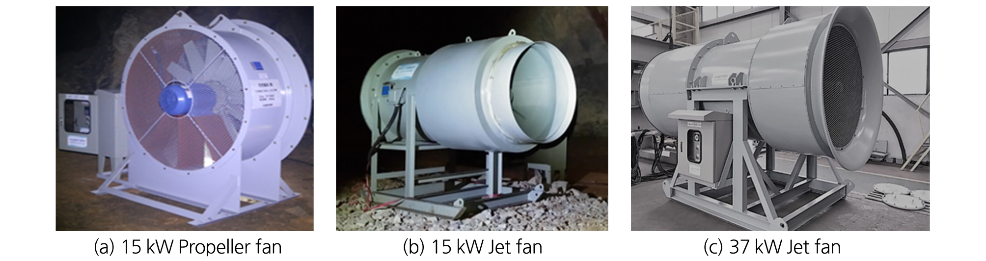
Table 1. Fan specifications for CFD analysis
Table 2. Conditions of CFD analysis
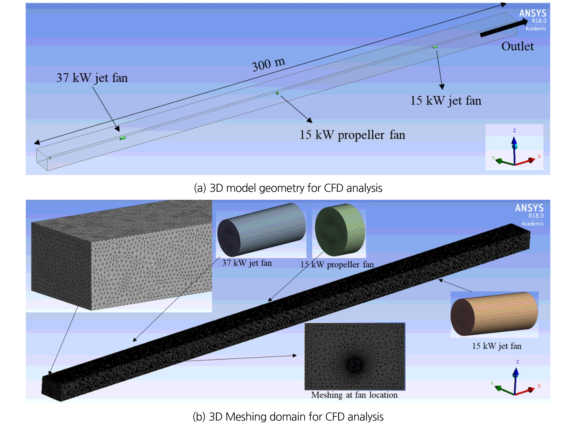
Fig. 2 (a) shows 3D model geometry of airway and the three fans studied in this study: 15 kW propeller fan, 15 kW jet fan, and 37 kW high-pressure jet fan. The meshing domain can be seen in Fig. 2 (b). The CFD analysis conditions are summarized in Table 2. The turbulence model was employed in this CFD study.
3.2 Analysis of the auxiliary unducted-fan installation location
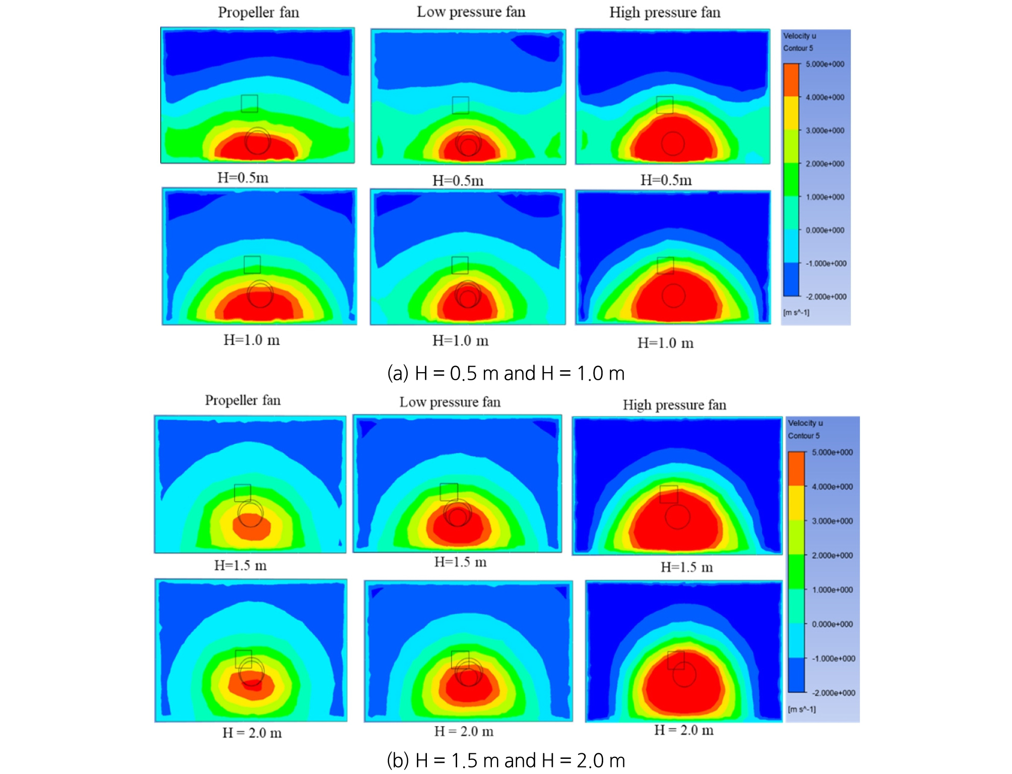
Fig. 3 shows the velocity distributions over the vertical cross-section at 20 m downstream of the fan. Fig. 3 (a) shows that in the cases of fan installation height of 0.5 and 1.0 m in, considerable momentum loss is likely to occur due to the collision of the air stream with the floor, and much less loss can be observed in the cases of 1.5 and 2.0 m shown in Fig. 3 (b). A similar pattern can be shown with all three fans. Considering that the installation height of the auxiliary fan in large-opening mine is less than 1.0 m in most of the cases at local limestone mines, the current practices adopted from the experiences at the small or medium-opening coal and ore mines can be easily considered one of the major causes of the low ventilation efficiency. This analysis indicates that the height of the auxiliary fan should be more than 1.5 ~ 2.0 m to reduce the energy loss due to the collision of the jet stream to the airway sidewalls.
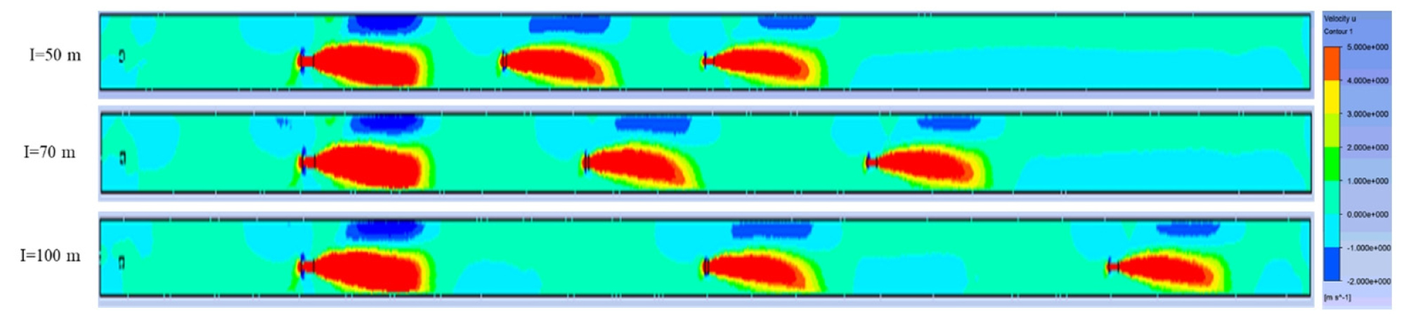
As the airway is getting longer and longer, only one auxiliary fan may not be enough to meet the ventilation requirement in large-opening limestone mines. Multiple fans installed in series are necessary to secure auxiliary ventilation efficiency in the long blind entry. Fig. 4 shows the longitudinal velocity profiles of the airflow with the different fan intervals of 50, 70, and 100 m, respectively. It can be seen that there was not much difference among them in terms of the reach of jet stream faster than 5.0 m/s. However, as the interval increases, the airflow velocity at the inlet side of the downstream fan decreases; in the case of 100 m, the inlet-side velocity was in the range of 1.0 ~ 2.0 m/s. Thus, this implies that in the case of multiple fans installed in series the suitable fan interval should not be far more than 100 m to ensure ventilation efficiency of the fans.
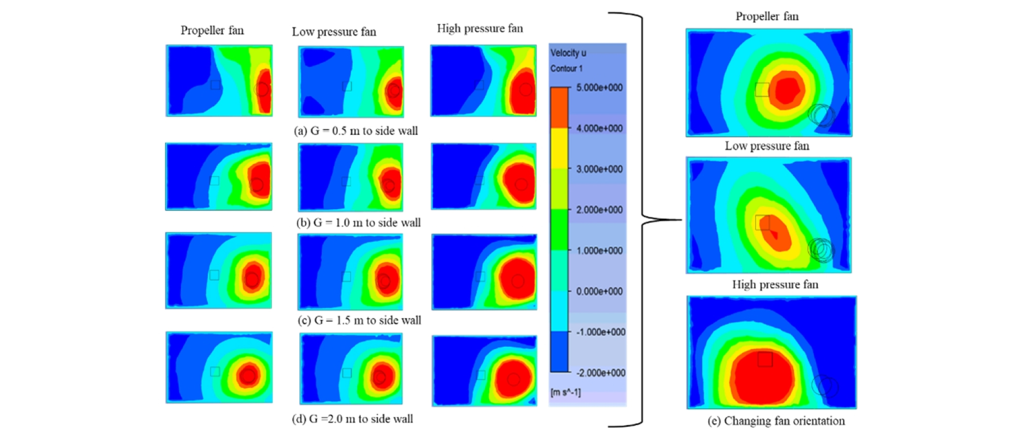
In the ideal case, the fan should be placed at the center of the airway cross-section to minimize the collision of the jet stream. However, installing a fan at the center is impossible in most of the cases where the entry is used as the haulage way. Fig. 5 illustrates the cross-sectional profiles of the air velocity by varying the gap length between the fan and entry sidewall. Similarly, in the case of the gap length of 0.5, and 1.0 m shown in Fig. 5 (a), and (b), the high energy loss of jet stream was observed due to the collision with the sidewall, while it was reduced for the gap length of 1.5 and 2.0 m shown in Fig. 5 (c), and (d). The results show that the gap length between fan and sidewall should be larger than 1.0m. Fig. 5 (e) shows the results when the fan was horizontally rotated toward the center at approximately 17 degrees. It implies that changing the fan axial angle toward the center horizontally or vertically can reduce the possibility of the jet stream collision and subsequently improve ventilation efficiency.
3.3 Analysis of the auxiliary fan layout in a single blind airway
Lee and Nguyen (2015) indicated that in large-opening limestone mines, the high-pressure axial-flow fans used commonly have excessive capacity and low efficiency. The low-pressure axial-flow fan was strongly recommended for local limestone mine due to the potentials of higher ventilation efficiency, less capital and operating costs. In this study, a low-pressure 15kW propeller fan was introduced for the analysis and its characteristics are listed in Table 1. The number of fans, fan location, and fan operating mode were the study topics. For the study, three scenarios summarized in Table 3 were designed to investigate the ventilation efficiency of the unducted fan system in a single-blind airway, 230 m (long) x 10 m (wide) x 8 m (high). The CFD analysis conditions were same as in Table 2.
The optimal ventilation system is the one where the intake and return airflows are separated and also sufficient enough to dilute the contaminants away from the working sites. In the analysis scenarios, the gas concentration profiles in the working area were simulated to evaluate the ventilation efficiency. For the CFD simulation, two heavy trucks located at the dead-end working face were assumed to emit CO continuously at the rate of 0.613 m3/h (Road design guidelines, 2010). The total simulation time was 30 minutes. The CO concentration distribution was used as the criterion for evaluating the gas dispersion efficiency of fan operation. The results are discussed in the following sections.
Table 3. Scenarios for the auxiliary unducted-fan layout in blind airway
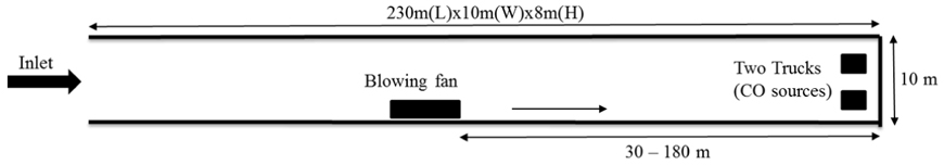
3.3.1 Scenario I with one blowing fan
Fig. 6 shows the air velocity and CO concentration contours on the horizontal planes over the entire 230 m-long airway at the height of 2.0, 4.0 and 6.0 m. The airflow velocity observed near the working face was nearly 2.0 m/s. However, considerable recirculation of airflow was observed near the fan location with the velocity of 0.4-0.6 m/s at the height of 2.0 and 4.0 m. Since even with the fan operation, air exchange through the inlet plane was extremely limited, it indicates that most of the air in the working domain continued to be recirculated.
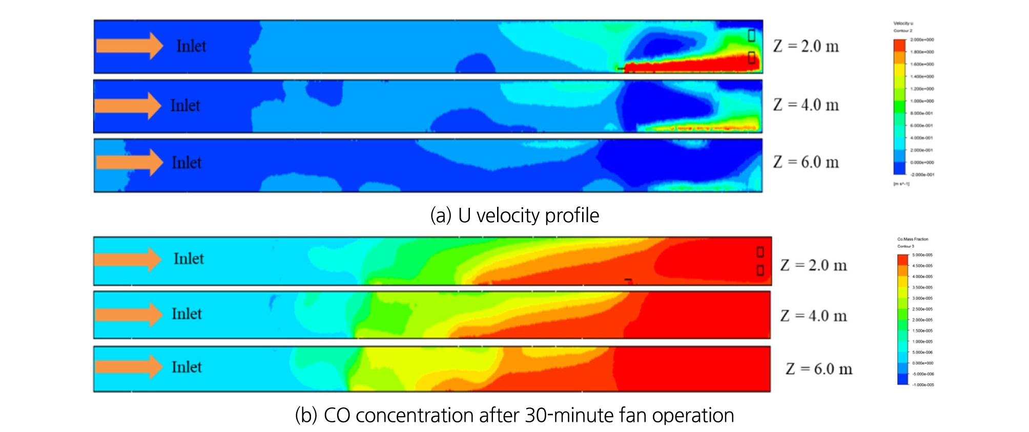
This observation is well described in Fig. 6 (b) displaying the CO concentrations after the 30-minute simulation in case of the fan at 50 m downstream. CO concentrations on the most portion of the cross-section were above 50 ppm within 150 m from the face as shown in Fig. 6 (b), mainly due to the recirculation. This indicates that the fast-moving airstream discharged by the fan could reach the working face and subsequently the polluted air was discharged through the upper half of the airway. However, most of the outby airflow was sucked into the fan and recirculated. This aggravated the air quality near the working place as time went by.
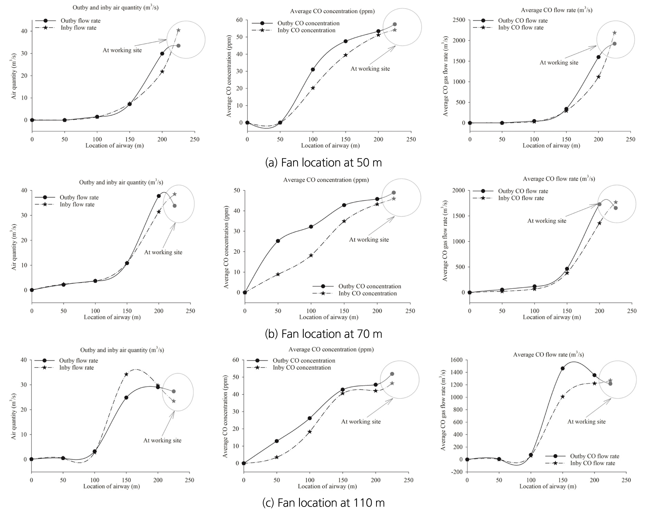
Inby and outby airflow rate, average CO concentration on the cross-section and average CO flow rate in the in-and outflows are plotted by distance in Fig. 7. The origin of the x-axis is the inlet portal; the working face is at 230 m. The fan locations are 50 m, 70 m, and 110 m downstream of the working face. The CO flow rate in m3/s is used as an indicator of the fan ventilation efficiency. Comparisons of the CO flow rates in the in- and outflow clearly show that within the working space ahead of the fan, the CO concentrations and flow rates in the outflow exceeded those in the inflow. This implies that as shown in Fig. 7 (a), the air was recirculating between the fan, and the working face and CO generated by trucks at the face continued to be added to the flow. However, Fig. 7 (b) shows how the mechanism of the turbulent diffusion is related to the diffusion of CO passing the fan; even though the air velocity was nearly zero, the CO concentration was still high even in the upstream. However, there was no inflow and outflow of the air and CO observed through the inlet portal. A similar pattern can be observed in Fig. 7 (c).
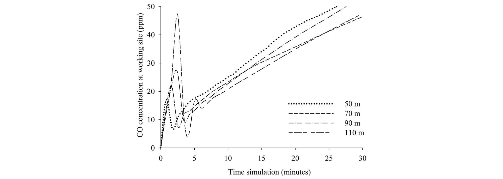
As aforementioned, the air recirculation and the continuous CO emission from two stationary trucks at the face, aggravated the air quality. This relationship is well demonstrated in Fig. 8 where the CO concentration at the working site was monitored during the 30-minute simulation. After the stabilizing five minutes, CO concentration kept on increasing regardless of the fan location and reaches 50 ppm approximately after 30 minutes. The case with one fan at 50 m shows the earliest arrival time of CO gas, even though the differences were not significant.
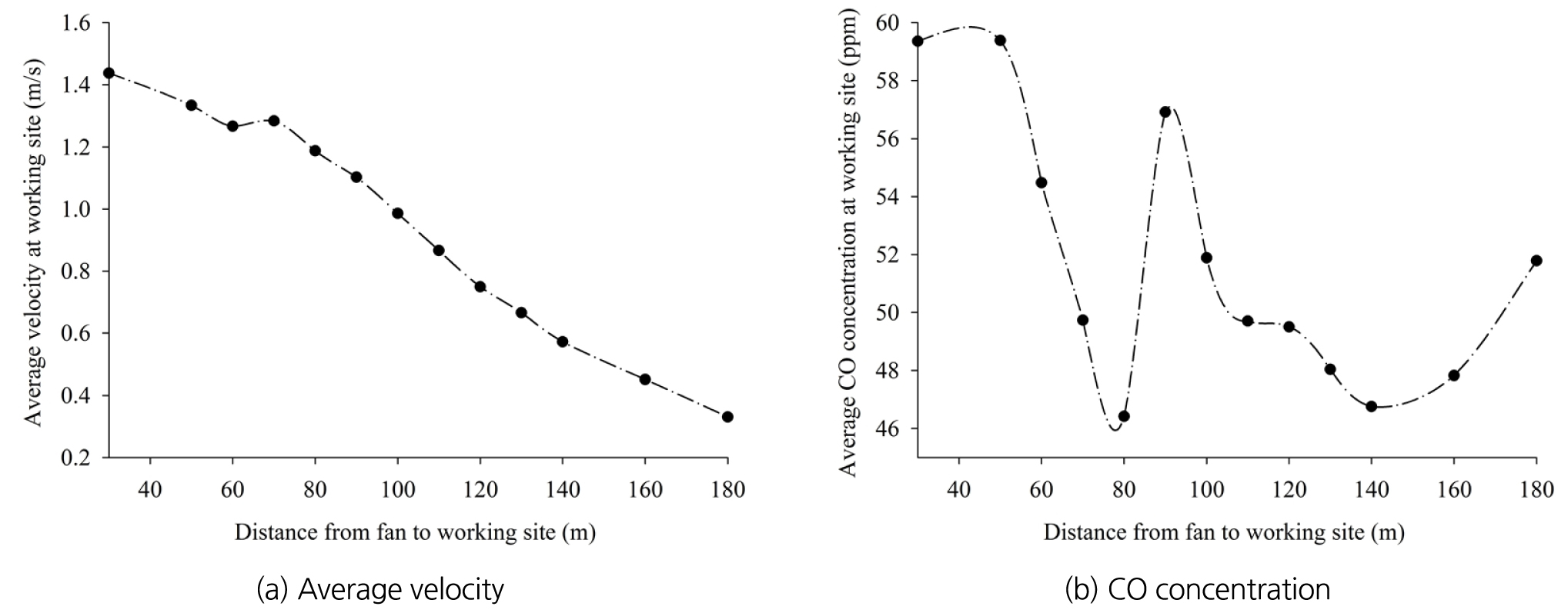
Change in the fan location significantly influenced the average velocity and CO concentration at the working site as plotted in Fig. 9. Fig. 9 demonstrates that the blowing fan operated at 70 - 80 m from the working face shows slightly better results than the other alternatives with respect to CO concentration at the working site. In this study, the working site was assumed to be the location at 5.0 m from the face. The average velocity ranged between 1.2 - 1.3 m/s at the working site. In Scenario I with one blowing fan installed close to the wall, separated in-and-outflow streams could be generated within the working space, even though most of the outflow was recirculated through the fan and subsequently the CO level gradually increased at the working site. However, the CO level at the working site was kept below 50 ppm within a 30-minute fan operation. The air exchange through the inlet portal was minimal.
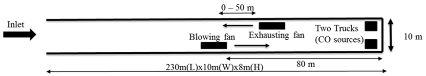
3.3.2 Scenario II with one blowing fan and one exhausting fan
According to the “new standards for mine safety technology” in Korea revised in 2017, the maximum allowable CO concentration in the workplace is 30 ppm (8-hr TWA) at the working site. Thus, Scenario I is not a proper ventilation system for local limestone mines. In Scenario II, one more fan was added to Scenario I and operated in exhaust mode. In Scenario II, one blowing fan was set up at 80 m from the working face, and one exhaust fan was installed on the opposite side of the airway at the locations 0 to 50 m downstream the blowing fan as in Table 2. The characteristics of the two fans were assumed to be identical.
When the two fans were installed side-by-side, the velocity contours on the horizontal plane at the height of 2.0, 4.0 and 6.0 m are plotted in Fig. 10. The in- and- outflows generated by two fans over the entire 230m-long entry were distinctively different from Scenario I. With a blowing fan close to the sidewall, the inflow stream was generated from the inlet portal up to the working face, while the outflow was observed on the opposite side with an exhaust fan. This observation is illustrated in the figure at 2.0 m high. The ventilation efficiency was improved significantly by adding one more exhaust fan to Scenario I.
Meanwhile, in Fig. 10(b), the CO concentration profiles in the case of the two fans installed side by side are shown. Relatively low CO concentration was observed in the whole airway, especially at the working site, compared with Scenario I. In Fig. 10(b), a limited space near the working face shows CO concentration of 50 ppm. At the inlet, inflow and outflow of CO could be easily observed. In this case, the average CO concentration in the whole space was found to be about 31 ppm.
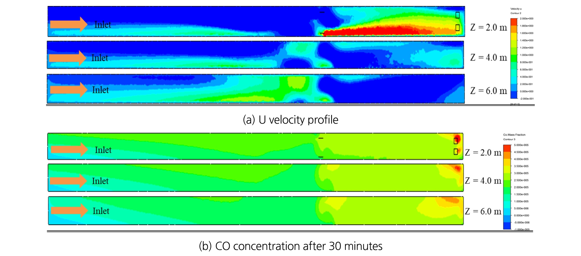
Fig. 11 shows the outby and inby air quantity, average CO concentration and average CO flow rate in case of the longitudinal distance between two fans of 0 m, 30 m, and 50 m, respectively. It indicates that the separation distance between blowing and exhaust fans clearly affects ventilation efficiency. In Fig. 11(a) for the fan separation distance of 0 m, the average of outby and inby air quantity are 4.0 and 7.0 m3/s, respectively. The relatively large difference between these flows implies that the contaminated air in the working space can be replaced with the clean intake air and then effectively disperses CO out of the working space. At the inlet portal, the average outby CO flow rate was 32.5 m3/s, much higher than the inby flow rate of 14.3 m3/s.
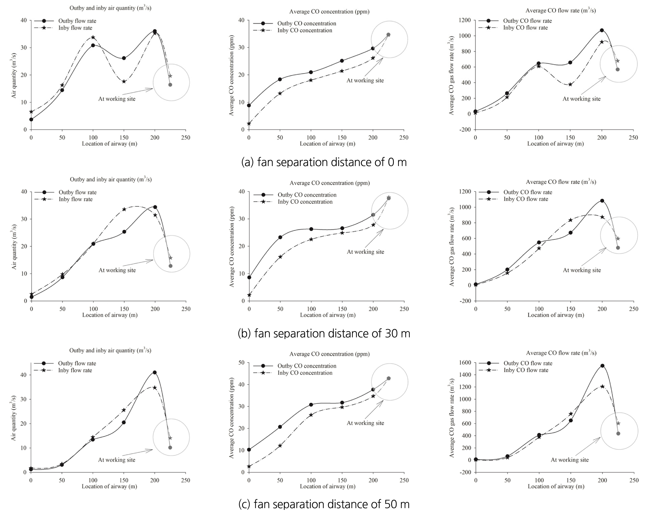
Fig. 11 (b), (c) shows the cases of the fan separation distance of 30 m and 50 m and similar results are observed. However, as the fan separation distance increases, the difference between inby and outby flow rates decrease; the outby and inby flow rates were 1.2 ~ 1.5 m3/s and 1.7 ~ 2.5 m3/s. Since the exhaust efficiency decreased with increasing separation distance, CO centration near the working face was higher, showing the range of 37 ~ 43 ppm in Fig. 11 (b) and (c). Fig. 12 illustrates the CO concentrations at the working site during a 30-minute simulation. As described in Fig. 11, CO concentration at the working site was 29 ~ 30 ppm for the separation distance of 0 ~ 30 m and 44 ppm for 50 m; higher CO concentration was observed with the larger separation distance between blowing and exhaust fans. Hence, the separation distance of 0 ~ 30 m was found to show better results to dilute CO at the working site in the blind airway.
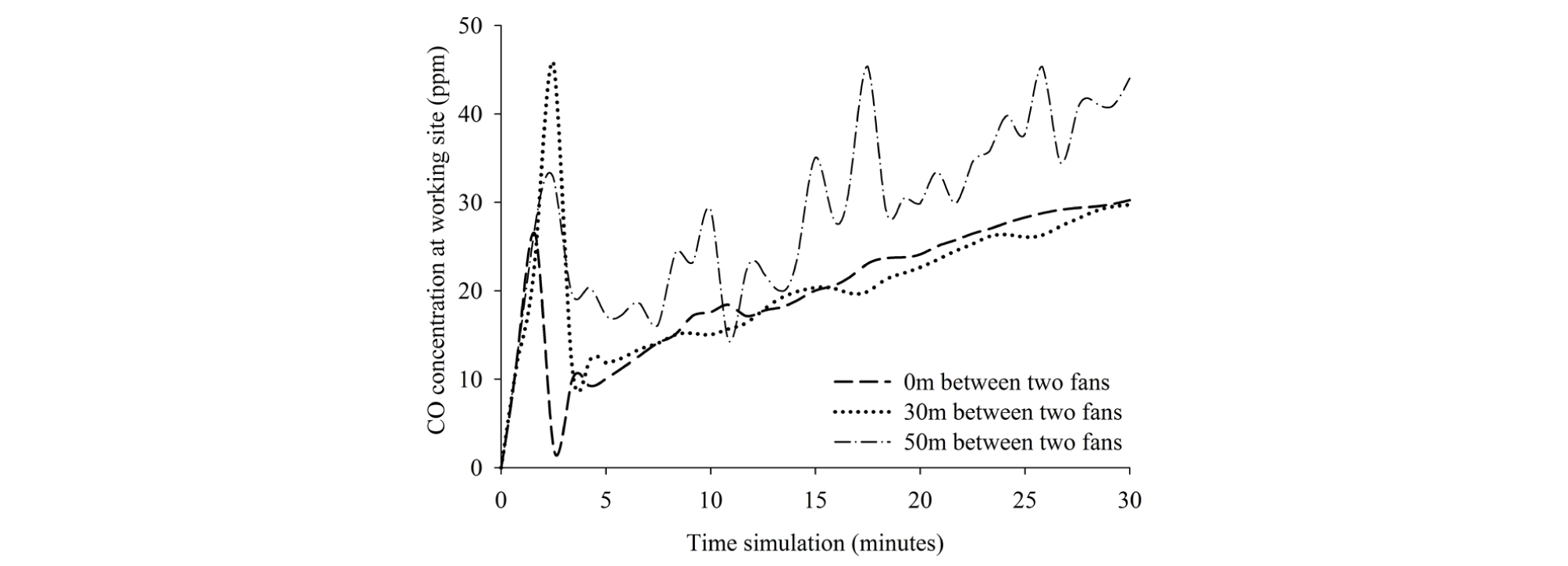
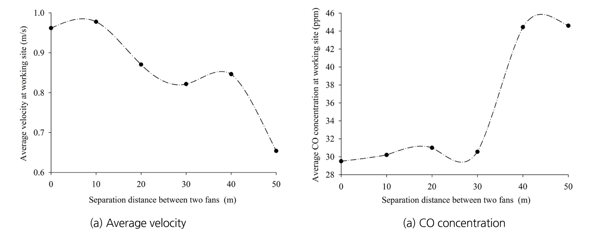
Fig. 13 shows that two fans separated by 0 ~ 30 m lead to relatively higher average air velocity and subsequently lower CO concentration in the working area.
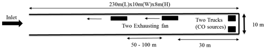
3.3.3 Scenario III with two exhaust fans in series
Scenario III was designed to evaluate the ventilation efficiency of the two exhaust fans installed in series. The distance from the first fan to the working site was 30m and the interval between two fans ranged from 50 to 100 m. The details of Scenario III can be seen in Table 2.
The longitudinal velocity profiles by height in the case of two exhaust fans 50 m apart are plotted in Fig. 14. The results were significantly different from Scenario I and II. The high velocity of the outby flow was observed at the height of 2.0 - 4.0 m due to the exhaust operation. On the contrary, the velocity of inby flow was relatively low over the entire airway.
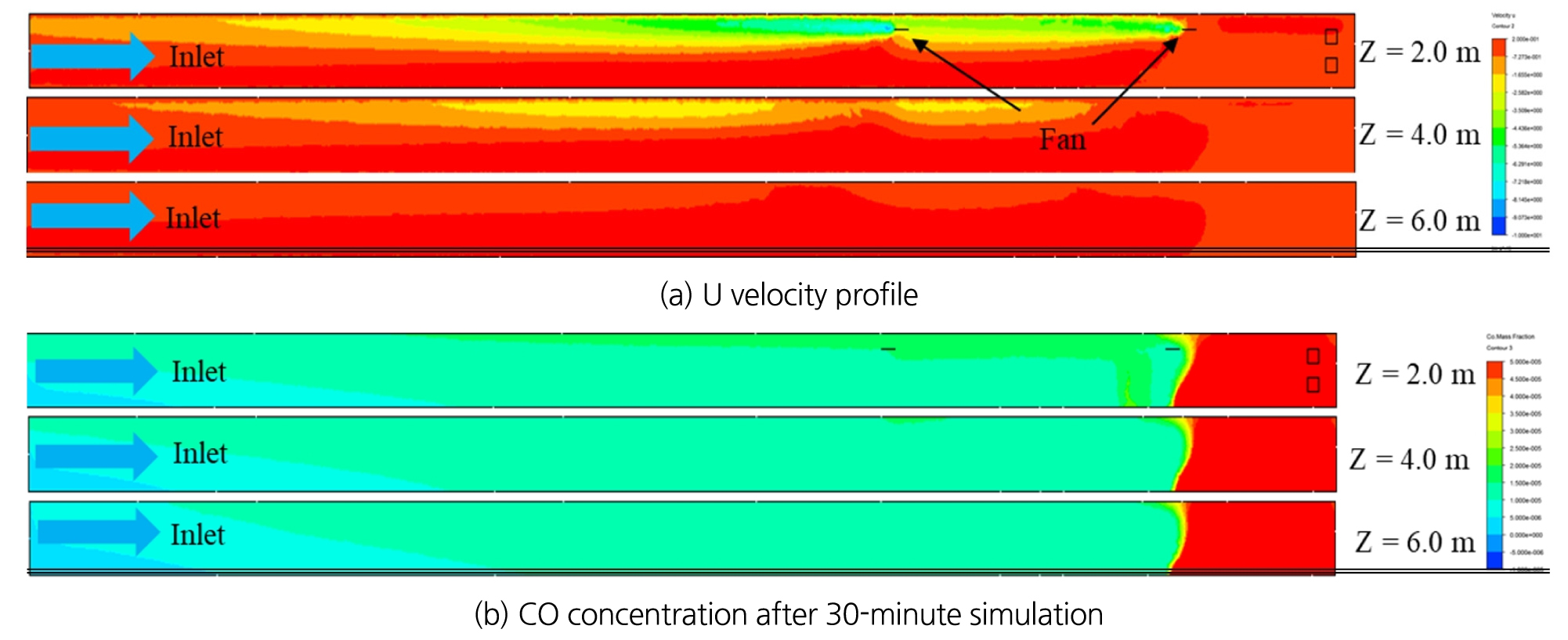
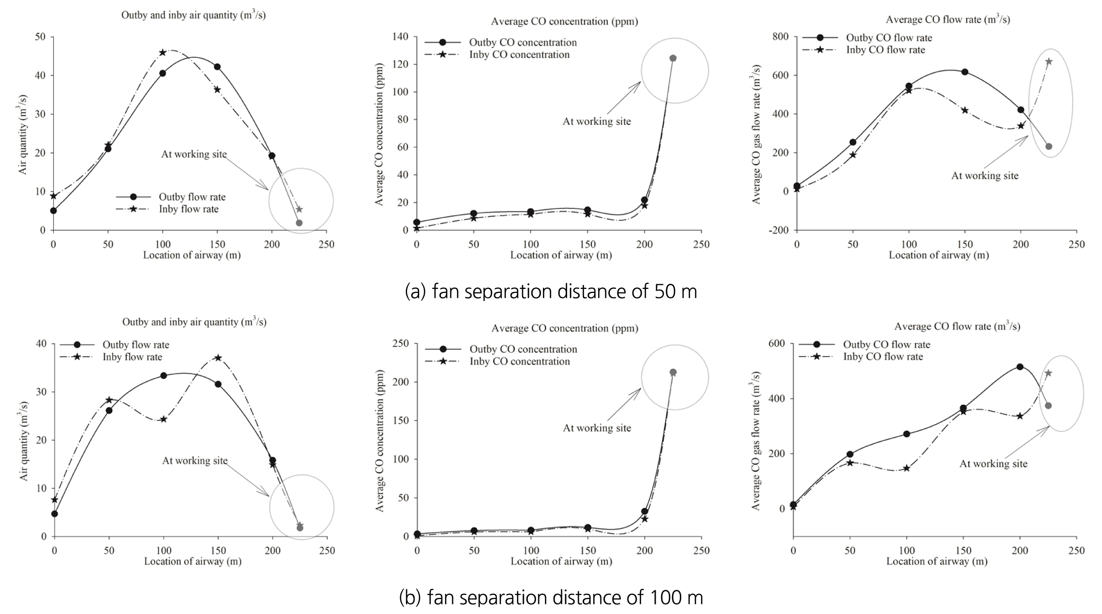
This low inby-flow velocity influenced the dilution of contaminated air. As shown in Fig. 14 (b), CO was in the range of 15 ~ 20 ppm in the section from the inlet portal to 150 m, but the extremely high level of CO was observed near the working face during the 30-minute simulation. The CO concentration reached 120 ppm near the face after 30 minutes of fan operation. The airflow rate, CO concentration and CO flow rate in the outby and inby airflows are plotted in Fig. 15. As forementioned, the average outby and inby flow velocities were extremely low at the working site. Fig. 15 (a) shows the case of two fans separated by 50 m; the average inby and outby airflow rates were 7.62 m3/s and 4.68 m3/s, respectively. However, near the working face, those flow rates were reduced to 2.33 m3/s and 1.75 m3/s. This led to the insufficient replacement of the contaminated air near the working site. CO concentration was maintained in the range of 10 ~ 13 ppm in the section from the inlet portal to 200 m locations, while it increased rapidly up to 124 ppm at the working site. In the case where two fans were separated by 100 m, the concentration was even higher; it reached 212 ppm at the working site as in Fig. 15 (b).
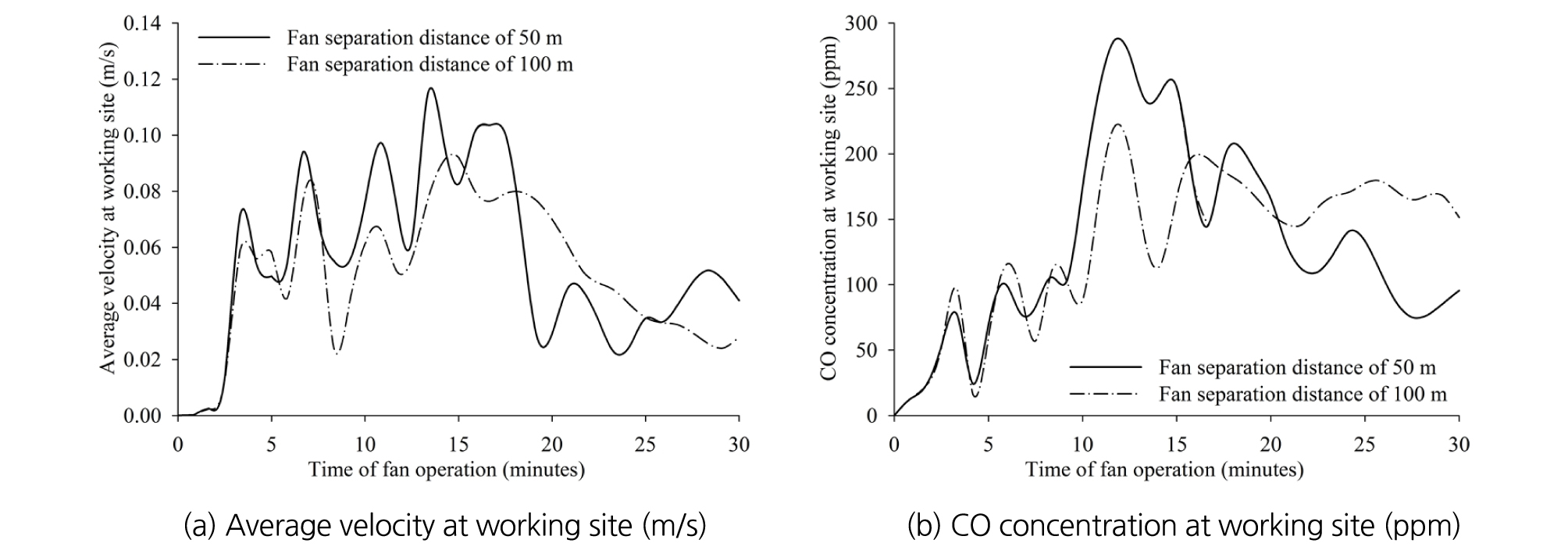
The results observed during the 30-minute simulation are plotted in Fig. 15. Due to the effect of exhaust mode operation, the low average velocity of 0.03 ~ 0.04 m/s was measured at the working site. As shown in Fig. 16(b), insufficient replacement of the air near the face resulted in low dilution efficiency and thus the high level of CO. After the 30-minute simulation with two exhaust fans in series separated by 50 m and 100 m, high CO concentrations of 95 ppm and 152 ppm were measured at the face. Thus, the CFD analysis of two exhaust fans in series shows that the ventilation efficiency was the worst among the three scenarios due to the extremely low exhaust efficiency of two fans installed in series near the working site despite the higher rate of air exchange through the inlet portal.
3.4 Comparisons
The CFD analysis in this study indicated that the ventilation efficiency in the blind working site could be improved by the appropriate installation of auxiliary fans. Scenario III with two exhaust fans in series was one of the worst auxiliary ventilation systems in terms of the air replacement and contaminant dilution efficiency. This study shows that the ventilation efficiency can be evaluated by the inby-and-outby flow rates and CO concentration within the working space. These two evaluation criteria are closely related to the air replacement and contaminant dilution efficiency of the system. In Fig. 17, the analysis results of all the cases studied in this study are summarized for comparison. Fig. 17 (a) shows that the average velocity at the working site was extremely low for the system only with fans in the exhaust mode. While its average velocity was in the range of 0.03 ~ 0.09 m/s, the case with the blowing fans showed a higher average velocity of 0.32 ~ 0.73 m/s. Due to the low airflow replacement by the exhaust system, the highest CO concentration of 738 ppm was detected in the case of one exhaust fan system. Among the 7 cases summarized in Fig. 17, the case with one blowing and one exhaust fan maintained the lowest CO concentration level near the working area.
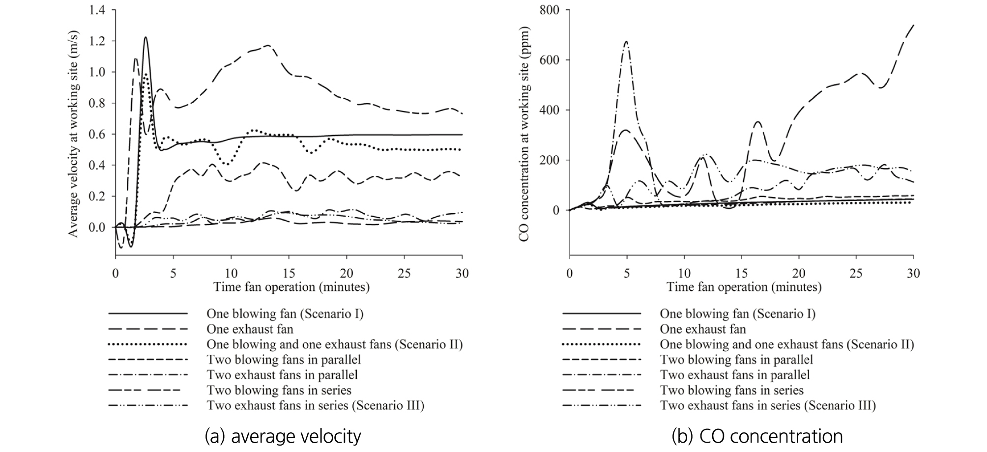
Table 4 summarizes the analysis results plotted in Fig. 17; it includes the in-and-out flow rates and the volume of CO above 30 ppm in all cases of the unducted fan system. Even though operating fans in exhaust mode generated higher in-and-outby flow rates than fans in blowing mode, the inby airflow induced by the exhaust fans could hardly reach the working place. This resulted in high CO level within the working space only by the exhaust auxiliary fans. However, when an additional blowing fan was added to the exhaust fan system in Scenario II, it was found that more inby fresh air could reach the working face and subsequently the CO level was lowered. Shown in Table 4, the system with one blowing and one exhaust fan induced the inby flow rate of 8.99 m3/s through the inlet portal and the outby air quantity of 6.91 m3/s; thus the volume of CO above 30 pm remained in the study domain was only 33 m3. When the exhaust fan was switched to the blowing mode, the two blowing fans showed much less ventilation efficiency and could induce only 0.13 m3/s. This inefficiency led to a significantly higher CO volume of 10.541 ~ 13.071 m3 after a 30-minute fan operation. Thus, even with the same number of fans, the results were completely different by changing the fan operating mode and the installation location. The CFD analysis results indicate that the unducted fan system with one blowing and one exhaust fan was the best system for diluting the contaminated air at the working space.
Table 4. Comparisons of the cases after 30-minutes fan operation
Fig. 18 shows the distribution of CO above 30 ppm after a 30-minute fan operation in all cases in Table 4. The case with one blowing and one exhaust fan clearly shows the minimum CO volume within the study domain as plotted in Fig .18 (c).

3.5 Comparisons with the ducted fan system
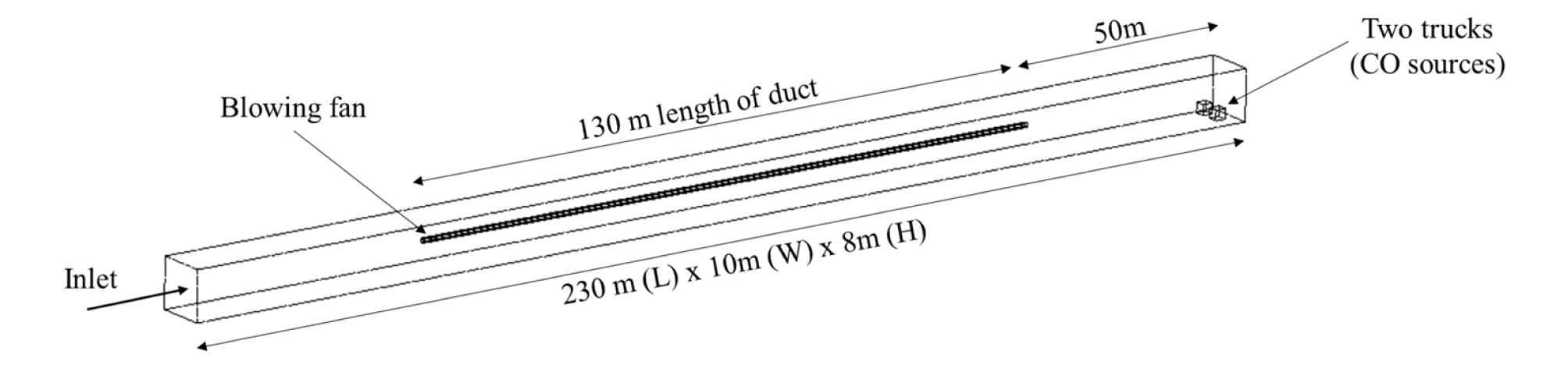
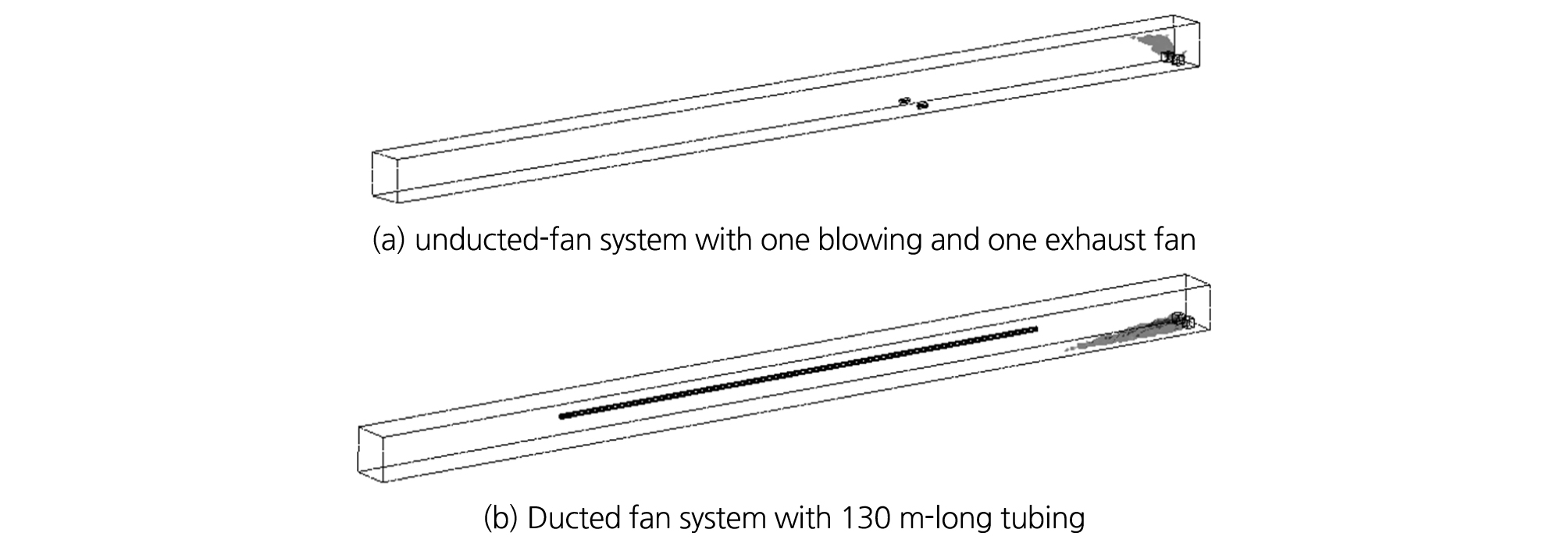
To compare the ventilation efficiency with the ducted fan system, one more Scenario was made. Fig. 19 illustrates the layout of a ducted fan system for CFD analysis. One blowing fan was installed with a 130 m-long tubing of 1.0 m diameter. The tubing was hung from the ceiling to supply air to the blind working site. The distance from the tubing tip to the face was 50 m. The other conditions for CFD analysis including fan specifications, entry size, and CO sources were identical to the other Scenarios.
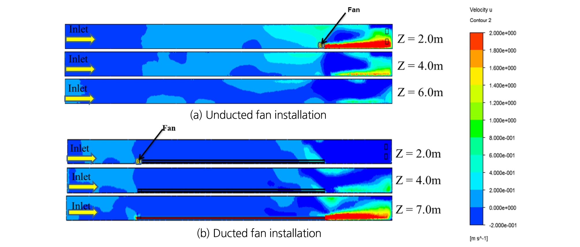
The longitudinal velocity profiles by height between unducted and ducted fan systems are compared in Fig. 20. The relatively high velocity of 0.6 ~ 1.1 m/s was observed in the working site for both systems. The case of the unducted fan system in Fig. 20 (a) shows considerable airflow recirculation near the fan location and the air velocity of 0.4 ~ 0.6 m/s at the height of 2.0 and 4.0 m. However, if connected to the tubing, most of the air recirculation near the fan location could be eliminated as shown in Fig. 20 (b). This implies that the ducted fan system is definitely better concerning to the air recirculation.
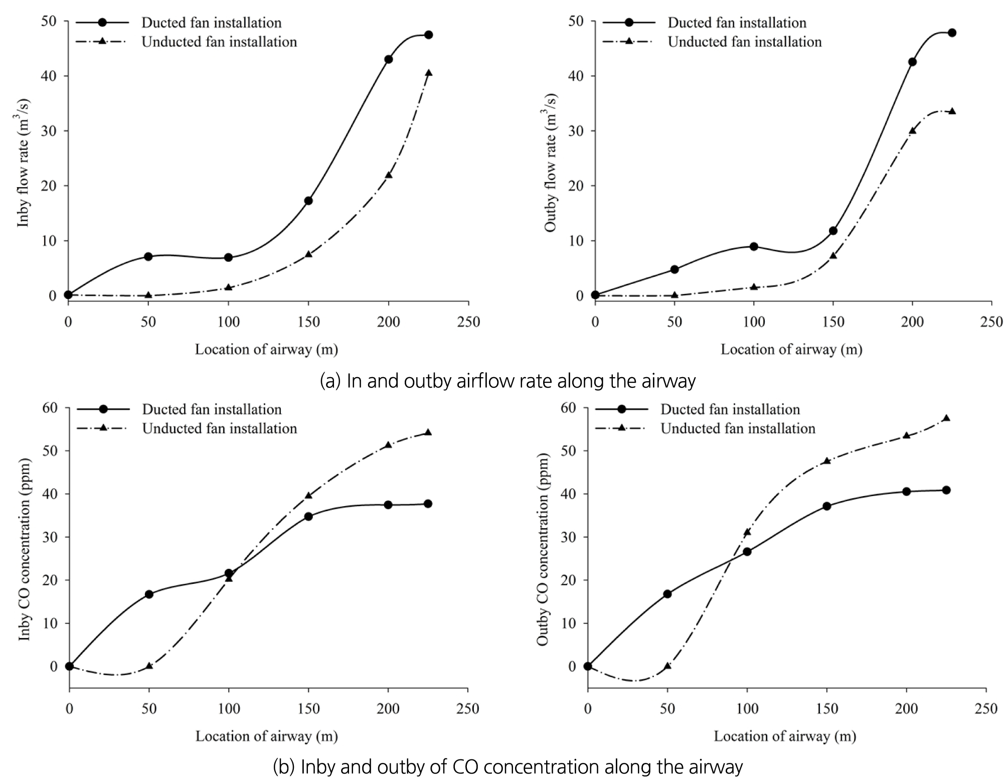
The in-and-outby airflow rates and CO concentrations along the airway are compared in Fig. 21. The ducted fan system showed relatively higher in-and-outby flow rates as shown in Fig. 21 (a). Even though the in-and-outby flow rates at the working site ranging between 40 ~ 47 m3/s in both systems were high, the flow replacement through the inlet portal which is defined as the difference between the inby flow and the outby flow was extremely low; 0.13 ~ 0.14 m3/s for the ducted system and 0.002 ~ 0.12 m3/s for the unducted system. This results led to higher CO concentration at the working place; CO at the face ranged between 37 ~ 40 ppm with the ducted system and 54 ~ 56 ppm with the unducted system. Thus, although the air recirculation was reduced by adding tubing to the unducted system, CO concentration level could not be lowered along the airway due to the low replacement at the inlet portal.
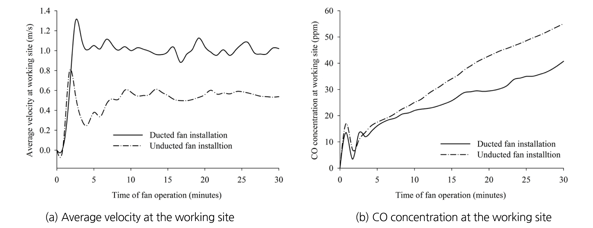
The average velocity and CO concentration at the working site observed during the simulation are compared in Fig. 22. It can be seen that the ducted fan system showed higher average velocity, 0.95 m/s compared with 0.50 m/s by the unducted fan system. Subsequently, CO concentration of 40 ppm was measured at the face by the ducted system and 55 ppm by the unducted system.
However, if the analysis target is shifted from the working face to the larger working area, the results were different. The volume of CO above 30 ppm after 30-minute fan operation is shown in Fig. 23. An unducted fan system with one blowing fan showed the CO volume above 30 ppm was 4.488 m3 and larger than 176 m3 with the ducted. Thus, it is clear that the ventilation efficiency of the ducted blowing fan system was better than the one blowing unducted fan system to ventilate the working space. However, the results were completely different if an additional fan was available for the system. The comparison was made between the ducted system and the unducted system with one blowing and one exhaust fan as in Scenario II. The ventilation efficiency of the unducted fan system was much better. As discussed in Table 4, the CO volume above 30 ppm with one blowing and one exhaust unducted fan was only 33 m3, compared with 176 m3 by the ducted system with 130 m-long tubings. In addition, the unducted system with one blowing and exhaust fan, the airflow replacement via the inlet portal was extremely higher than the ducted system with one blowing fan. While the in-and-outby flow rates were in the range of 6.91 ~ 8.99 m3/s with the blowing and exhaust fans without tubing, those of the ducted system ranged between 0.13 ~ 0.14 m3/s. Hence, this indicates that the unducted system with two fans showed higher air replacement and subsequently higher ventilation efficiency. Several problems such as leakage and difficulties in installation and maintenance with the ducted system have been experienced for a long time and those are still limitations of the ducted auxiliary ventilation system in underground mines. On the contrary, the unducted system can eliminate all these limitations of the ducted system and has the advantages of flexibility, easy installation and low management cost. Considering these circumstances and the results of this study, the unducted-fan system with two fans described in Scenario II is strongly recommended as an auxiliary ventilation method in the blind large-opening airway.
4. SITE STUDY WITH A UNDUCTED FAN SYSTEM
4.1 Test of a unducted fan system at mine site
The ventilation efficiency of an unducted fan system was tested at a local large-opening limestone mine in Gangwon province. Fig. 24 illustrates the test site where the whole working space is connected to the main haulage way by a single airway. The 250 m-long straight segment of the dead-end entry is 10 m wide and 8 m high. As in Fig. 24, one free-standing vane-axial 37-kW high-pressure fan was installed close to the sidewall to supply air to the working site, and the distance from fan to the dead-end working face was about 120 m. Table 5 describes the characteristics of the fan used.
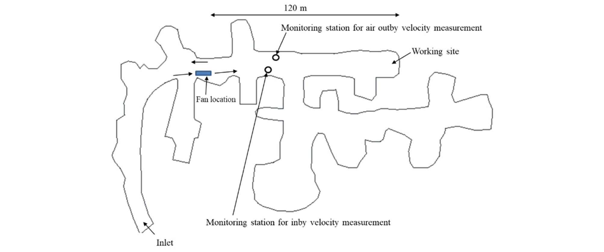
Table 5. Characteristics of the fan used for the test
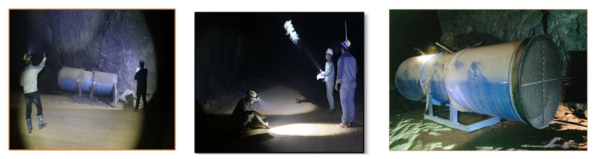
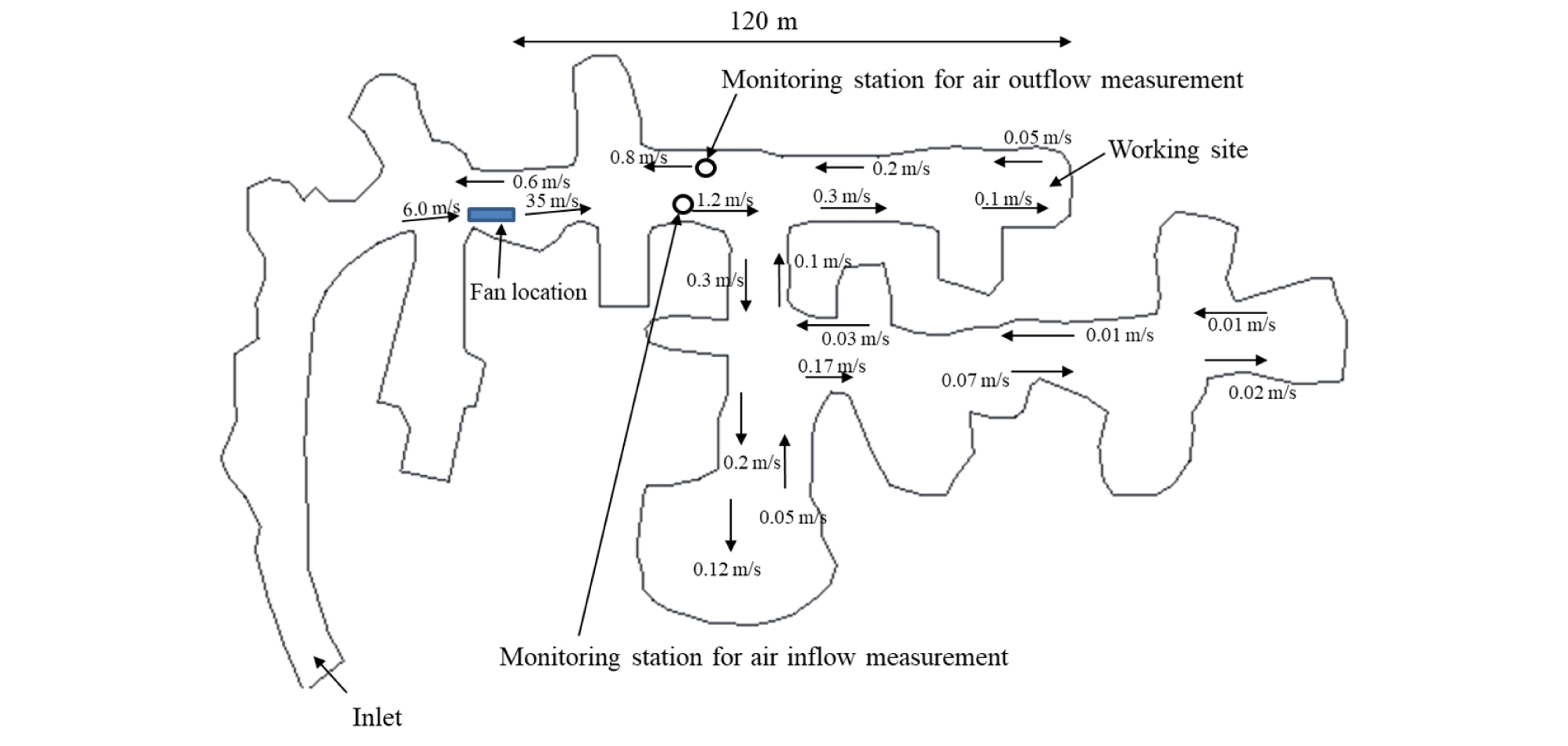
Hot-wire anemometers were used to monitor the average velocity at several positions within the experiment site. Smoke tubes were also used to identify the direction of airflow showing ultra-low velocity. Fig. 25 shows the unducted fan and smoke tube measurement. Velocity measurements were shown in Fig. 26. The fan discharge velocity measured at the outlet was 35 m/s. The air was supplied into the dead-end working area along the same side as the fan and was also flowing out along the other side. The average inby and outby velocities measured near the working face were 0.05 m and 0.1 m/s, respectively. The jet stream discharged from the fan lost a substantial portion of the kinetic energy due to the collision to the sidewall. This indicates that installing a fan in proper manners is critical for determining the ventilation efficiency; the location, discharge angle, installation height and the gap between fan and wall are some of those variables to take into consideration to enhance the ventilation efficiency. There were two fixed stations to monitor the inby and outby air velocity at both sides of the airway. The measurements are compared with the CFD analysis output in the subsequent section. The CFD analysis conditions can be seen in Table 2.
4.2 CFD analysis of the ventilation efficiency
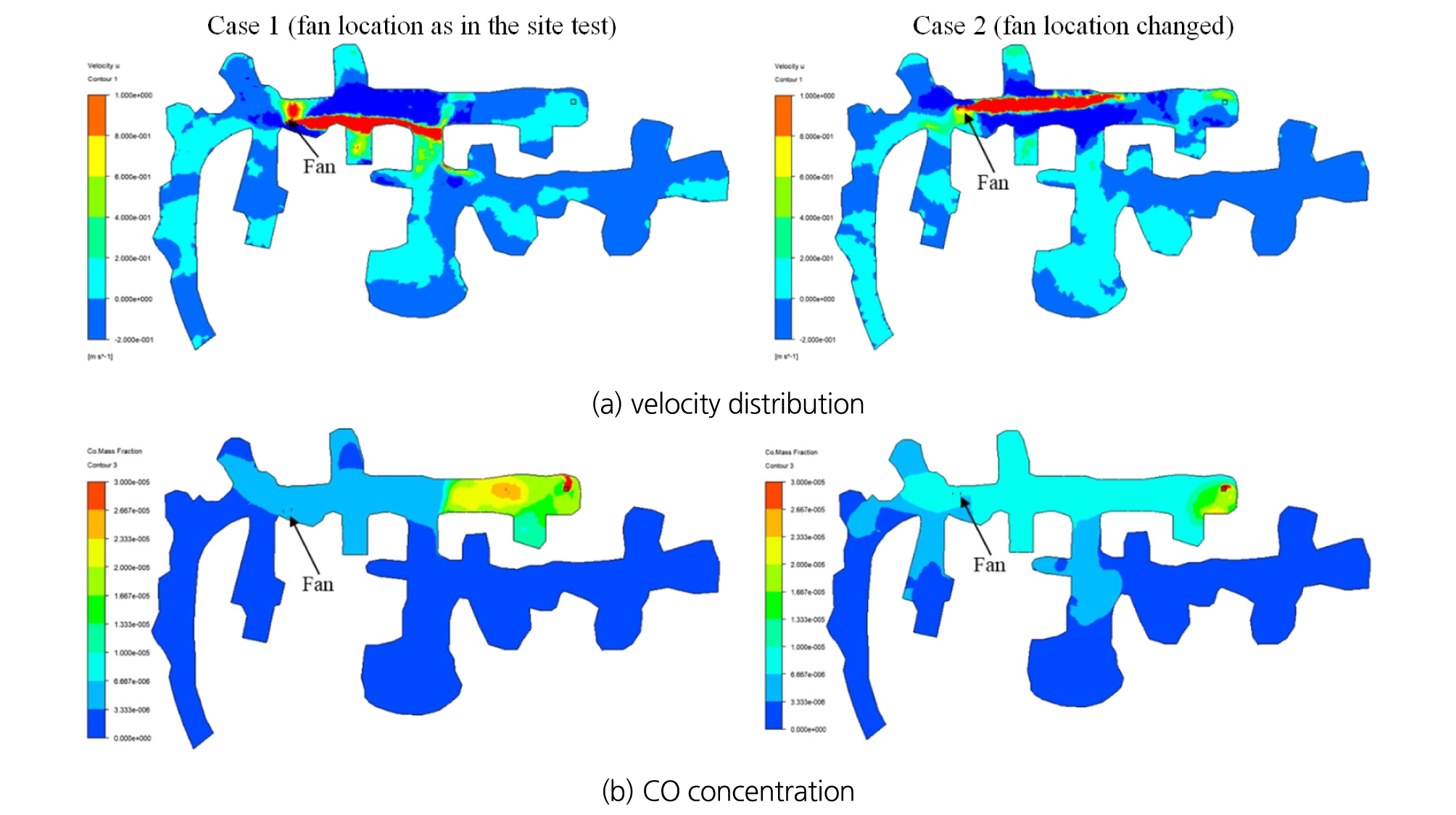
The aforementioned results indicated that the proper installation of the fan is critical to determining the ventilation efficiency. Fig. 27 shows the CFD analysis for two cases: Case 1 for the same system as the site test and Case 2 with the fan at a different location to assess its effect on the ventilation efficiency. In Case 2, the fan was moved to a location to minimize the possibility of collision of the jet stream with the airway sidewalls. In Case 1 where the jet stream generated from the fan collied with the sidewall immediately after being discharged, its flow length colored red in the figure was shorter compared to Case 2 where the fan was relocated to minimize the possibility of collision. Therefore, Case 2 clearly showed higher velocity distribution near the working faces in Fig. 27. As predicted, higher velocity distribution in Case 2 led to lower CO concentration throughout the working space.
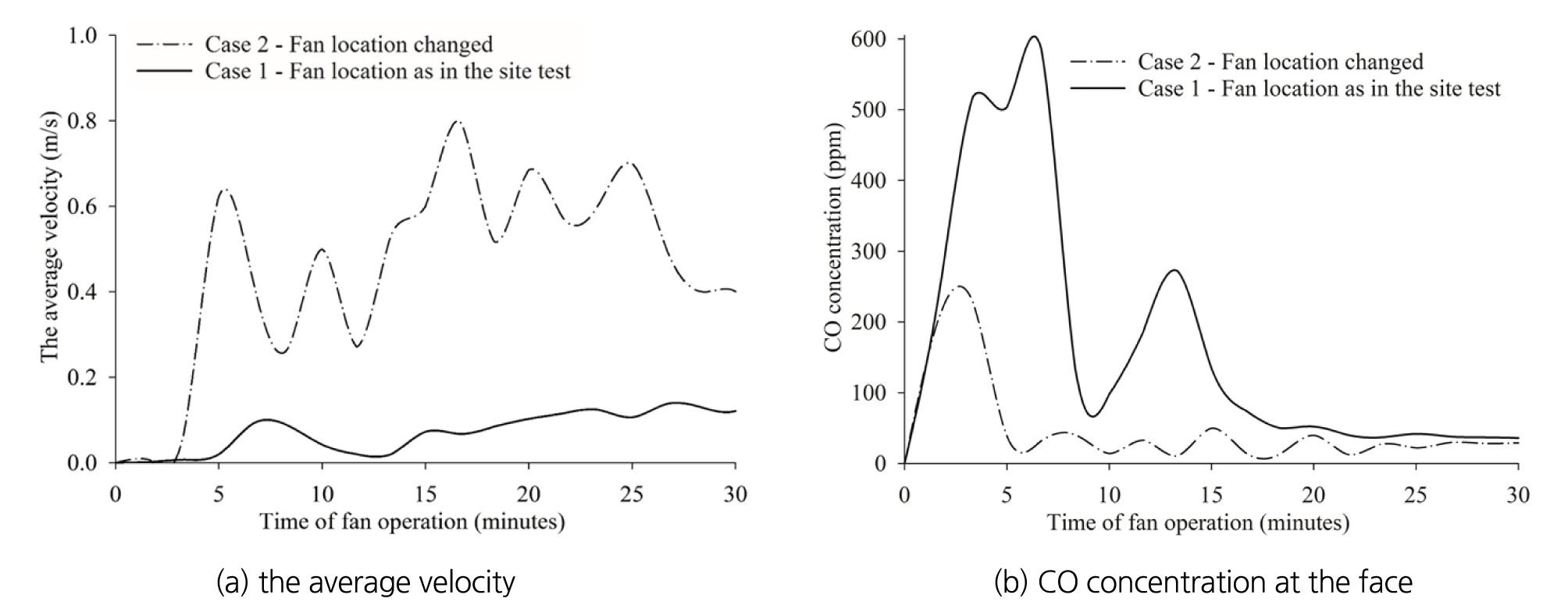
The average velocity and CO concentration at the working site are compared in Fig. 28. The average velocity at the working site in Case 2 was extremely higher than Case 1 with the same layout as in the site test. The average velocity of 0.43 m/s was measured at the working site in Case 2, compared with 0.08 m/s in Case 1 as shown in Fig. 28 (a). Fig. 28 (b) illustrates that 503 ppm in Case 1 after a 5-minute fan operation is much higher than 38 ppm observed in Case 2. This observation implies that fan must be installed to minimize the loss of jet stream flow energy in order to maximize the air supply to the working site.
4.3 Validity of the CFD analysis
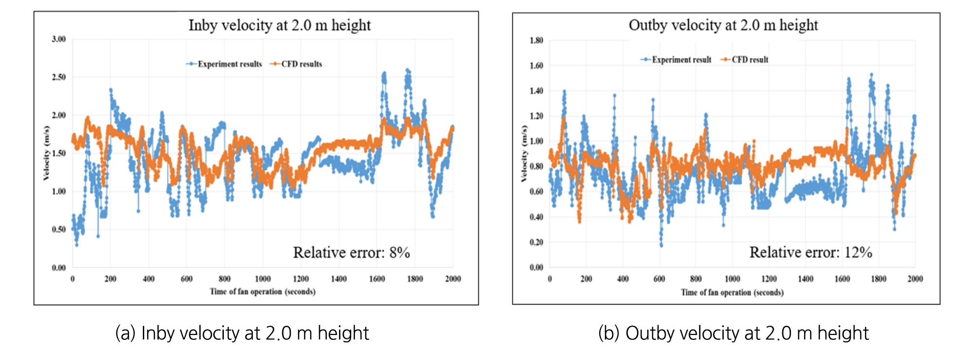
As described in Fig. 24, there were two monitoring stations for inby and outby velocities at both sides of the airway. The comparison between the CFD analysis and the site test was made in Fig. 29. The figure shows close similarity between them; the relative errors for the inby and outby velocities were 8 % and 12%, respectively. This implies that the CFD results drawn in this study were reliable to examine the ventilation system at the large-opening blind airways.
5. CONCLUSIONS
To assess the ventilation efficiency of the unducted fan system in blind working site, a series of auxiliary ventilation systems were evaluated by CFD analysis as well as site test. The effects of parameters such as fan operation mode, installation location, numbers and layout which are critical to the ventilation efficiency of the unducted auxiliary ventilation system were analyzed in terms of the effects on ventilation efficiency. This paper aims at providing a reliable and efficient solution to improve ventilation efficiency in local large-opening underground limestone mines. Several important results are summarized as follows:
1) To avoid excessive loss of kinetic energy of the jet stream discharged from a fan, the fan should be installed at least 1.5 m above the floor and 1.0 m away from the sidewall. These conditions can be achieved by adjusting the fan 3D orientation. In addition, when multiple fans are placed in series in large-opening limestone mines, the fan interval should be less than 100 m to maintain the fast-moving airflow through the consecutive fans.
2) In a single-entry blind working site, one blowing fan is not sufficient to supply fresh air enough to dilute the contaminated air in the working area. However, the unducted ventilation system with two fans, one blowing and one exhaust fan installed on the opposite sides is highly recommended as an efficient auxiliary ventilation system in large-opening mines. The two fan system shows higher air replacement rates due to the relatively larger difference between the inby and outby flow rates. Higher air replacement leads to lower contaminant concentration within the blind working area. The airflow exchange rate through the inlet portal is also high. Therefore, the two-fan system shows higher ventilation efficiency when the blowing fan is installed further away from the working face and the two fans are separated by 0 ~ 30 m.
3) The ventilation system with two exhaust fans in the series is found to be a poor scheme due to the low airflow rate supplied to the face and low subsequent air replacement efficiency. Therefore, it leads to extremely high contaminant concentration within the working environment. Hence, the system with two exhaust fans in the series can not be recommended for the blind site auxiliary ventilation scheme.
4) The site experiment with one 37 kW blowing fan shows that the low efficiency of fan installation led to the low velocity at the working site. The site study results show that fans must be placed to minimize the possibility of collision and maintain the high velocity of the airflow. Acquiring a certain difference between the inby and outby air velocities is critical to lower the contaminant level at the blind working sites. These results were well confirmed by the CFD analysis.
5) Ventilating large-opening blind working sites is a difficult task without a properly designed and managed auxiliary ventilation system. However, even with a well-engineered system, a low capital and maintenance cost system is also required at local limestone mines. This study shows that low-cost unducted auxiliary ventilation system with two fans, one blowing fan and one exhaust fan, can provide flexibility as well as high ventilation efficiency if designed correctly.
