

1. Introduction
1.1 Research background
1.2 Korean disposal system
1.3 Sensitivity analysis
2. Numerical Techniques and Algorithms
2.1 Coupled hydro-mechanical formulation
2.2 Numerical model description
3. Results and Discussion
3.1 Swelling pressure performance
3.2 Sensitivity analysis
4. Conclusions
1. Introduction
1.1 Research background
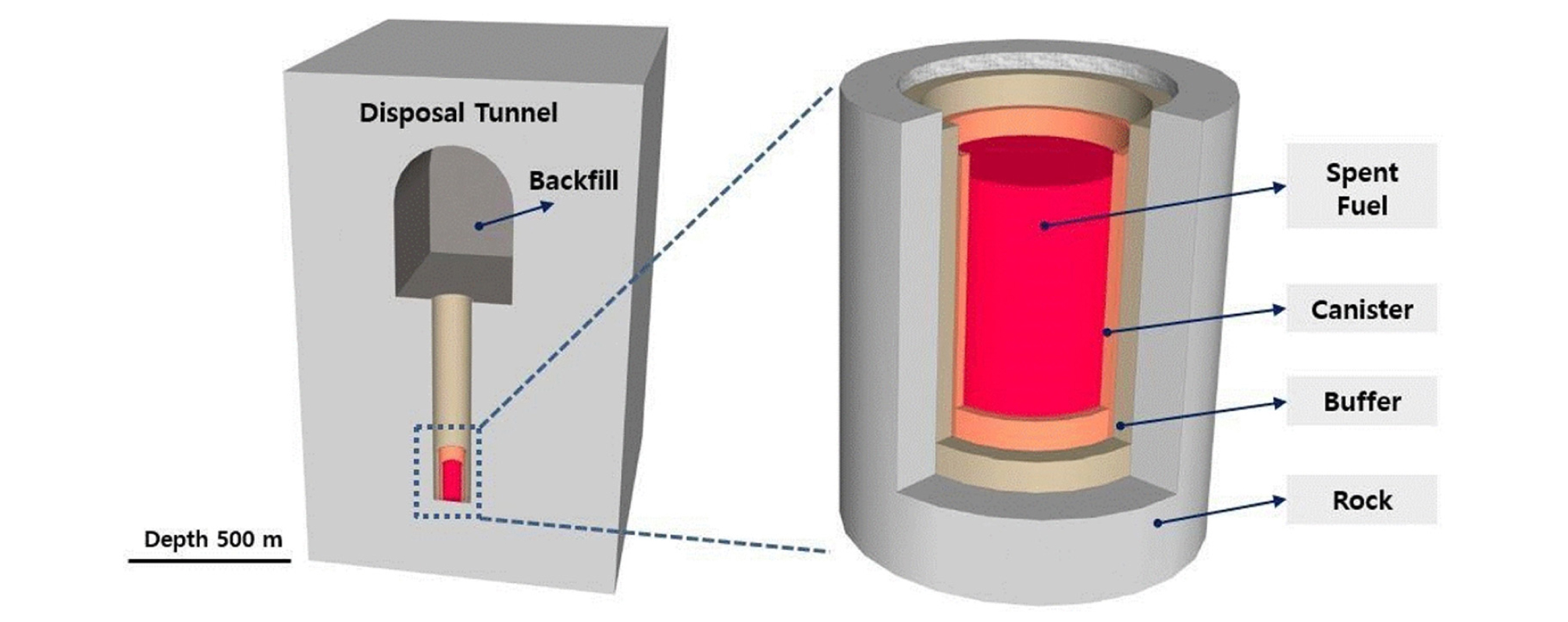
Since a spent fuel from nuclear energy sources releases decay heat and harmful radiation for extended periods, issues regarding radioactive waste disposal have been constantly emerged. Among various types of disposal systems, a deep geological system, where high-level waste (HLW) is safely isolated from human society by surrounding buffer, backfill and near-field rock, is preferred in most countries due to its safety and reliability.
In order to develop a disposal system considering these factors, accurate prediction of disposal system is required. Since the operation period of the deep geological repository is about 40-50 years and the retrieve period is about 50-100 years, it is necessary to predict the long-term behavior of the repository.
Disposal tunnels are excavated through controlled blasting techniques. Rock is considered to be the best repository because of its low permeability, high thermal conductivity, and ductility. Korea considered granite as a parent rock due to its high strength, resistance to weathering, and its nuclide absorbability.
Because the HLW emits heat and high radioactivity, disposal containers for strong HLW require great care in selecting, manufacturing and handling the materials. The HLW disposal containers must be able to store waste safely for a long period (usually 10,000 years). Disposal containers that require long-term storage of HLW in rock beds are made of corrosion- resistant materials and designed to withstand underground pressure and swelling pressure of bentonite cushioning materials. Failure to design a HLW canister can result in structural defects such as plastic deformation or cracks. Therefore, various structural analysis and thermal analysis should be performed in order to prevent the structural problems occurring in the canister. The canister considered in the Korean disposal concept is 1.02 m in diameter and 4.8m in length (Kwon, 2012).
If tunnels are closed without the backfill material, ground water flow path can be generated by the mechanical damage of the rock due to the stress acting in the underground. Therefore, it is common to install a backfill material in a disposal tunnel before closing the disposal tunnel.
A suitable backfill that meets the following objectives should be selected and used. The proper backfill should (1) improve the stability of tunnels, (2) maintain the expanding cushioning material around the disposal canister, (3) prevent the flow of groundwater to the tunnel, (4) do not change the properties of buffer and ground water, (5) be chemically stable for a long period of time (SKB, 1992). In the case of a disposal repository installed in a highly cracked crystalline rock, it is common to use the expandable bentonite with the crushing rock as a backfill material. In rock salt disposal facilities, crushed rock salt is considered as the most suitable backfill material.
In the concept of HLW disposal, bentonite which has low permeability and high swelling property is considered as a base material of buffer material. The main function of the buffer is to fill existing pores and to make the area around the HLW less permeable. This role is called as self-sealing, which is essential to establish a stable geological disposal system. Thus, the swelling property is a key element in the design and development of the deep geological repository and needs to be studied in depth.
1.2 Korean disposal system
Natural calcium bentonite or sodium bentonite is commonly used for a buffer material. In the Korean Disposal Concept (KRS), Gyeongju calcium bentonite, which is produced near Gyeongju is proposed as a buffer material candidate. In Korea, it is difficult to determine specific requirements of the buffer because field tests are difficult, so the performance criteria of general buffers are used.
Table 1. Performance criteria of the buffer (KAERI, 2008)
The main objective of this study is to determine the major factor which influences a swelling pressure in a deep geological disposal system. Factors selected through this study will be considered in the future establishment of the Korea buffer criteria. In addition, previous studies focused on a single factor affecting swelling pressure, this study focuses on the effect of various initial factors on the generation of swelling pressure.
1.3 Sensitivity analysis
A sensitivity analysis is the study which provides information on the impact of each assumption variable on predictive variables. In this study, the latin hypercube sampling (LHS), a statistical method, is used. The LHS aims to evenly distribute the samples over all possible values. It divides each input distribution by N intervals of equal probability and select one sample at each interval. It mixes the samples for each input to prevent correlation between inputs, whereas a random sampling is just a set of random inputs (McKay, 2000).
A metamodel is a simplified model of an actual model. Among the diverse methods, in this study, Gaussian Kriging model was adopted. The Gaussian Kriging model is defined as follows.
| $$y(x)=\sum_{j=0}^L\beta_jB_j(x)+z(x)$$ | (1) |
where {Bj(x), j=1, …, L} is the chosen basis over the experimental domain, z(x) is the random error, and βj is the unknown coefficient. Instead of assuming the random error is independent and identically distributed, it is assumed that z(x) is a Gaussian process with zero mean, variance σ2, and correlation function. The following correlation function of z, and hence of y, is the stationary family as follows.
| $$r(\theta;s,t)=Corr(z(s),z(t))=\exp\left\{-\sum_{k=1}^s\theta_{\mathit k}\vert s_{\mathit k}\mathit-t_{\mathit k}\vert^q\right\},\;\mathrm{for}\;0\;<\;\mathrm q\;\leq2$$ | (2) |
where θk is the unknown smoothing parameter, s is the number of design variables, and sk, tk are kth the components of the samples.
The total and partial variance can be expressed as follows.
| $$V(Y)=\int_{}^{}{f^2(x)dx-f_0^2}$$ | (3) |
| $$V_{i_{1...i_s}}(x_{i1},...,x_{is})dx_{i_1}...dx_{is}$$ | (4) |
Denote that s=1,..., k and 1 ≤ i1 ≤ ... ≤ is ≤ k. The first-order, second-order, and total-order indices can be expressed as follows.
| $$S_i=\frac{V_i}V\;\;\;\;\;S_{ij}=\frac{V_{ij}}V\;\;\;\;\;S_{Ti}=1-\frac{V_{\sim i}}V=S_i+\sum_{j\neq i}S_{ij}+...$$ | (5) |
Si gives the fraction of model output variance which is caused by the input i, averaged over variations in all other input variables. Total order sensitivity index STi, which is used when one would like to know all sensitivity indices of all orders in, measures the total effect of an input, including its first order effect and interactions of any order. The sensitivity index below 0.01 are considered as non-influential to the system.
2. Numerical Techniques and Algorithms
2.1 Coupled hydro-mechanical formulation
In this study, a commercial program referred as CODE_BRIGHT was used to perform an appropriate coupled hydro-mechanical(HM) numerical analysis. The major actions that affect the bentonite buffer are hydration due to the underground water inflow.
The crucial feature of the HM behavior described is that all the phenomena are strongly coupled. Transport of a vapor cannot be considered on its own, but it is a part of a cycle closed to the movement of liquid water in the opposite direction. The flow of liquid depends on the fracture of surrounding rock, degree of saturation and permeability of buffer (Gens et al., 2009).
The equations that govern this problem can be categorized into four main groups: balance equations, constitutive equations, equilibrium relationships, and definition constraints. Mass balance equations are performed for water and air instead of using solid, liquid, and gas phases.
Mass balance of water is present in liquid and gas phases. The total mass balance of water is written as:
| $$\frac\partial{\partial t}\left(\theta_l^wS_l\phi+\theta_g^wS_g\phi\right)+\nabla\;\bullet\;(j_l^w+j_g^w)=f^w$$ | (6) |
where fw is the external supply of water, θl is the mass of liquid, θg is the mass of gas, and is the flux of liquid and gas which dissolved in water.
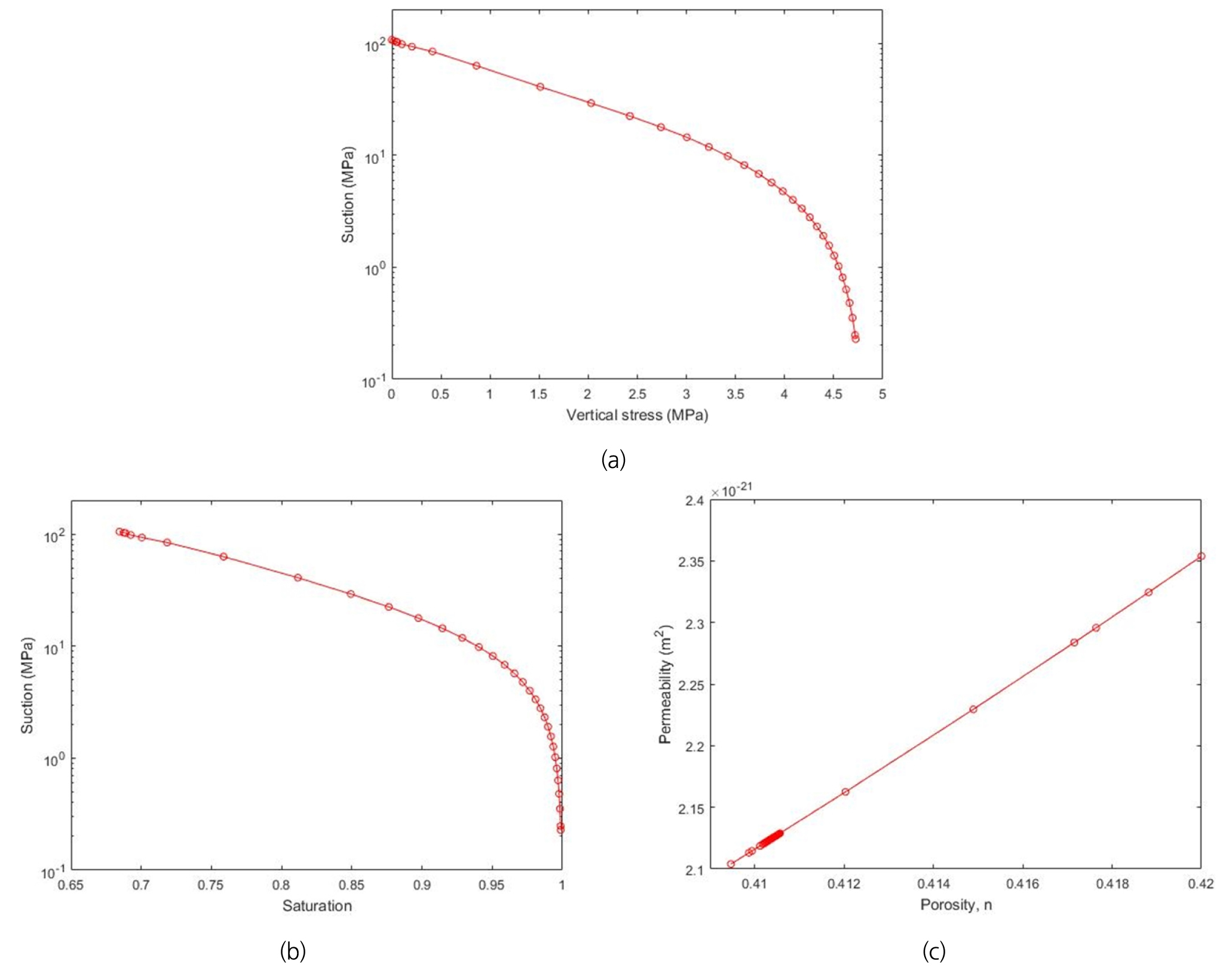
For the fluid flow in a surrounding rock to bentonite buffer, the Van Genuchten model retention curve is adopted. (van Genuchten, 1980)
| $$S_e=\frac{S_l-S_{rl}}{S_{ls}-S_{rl}}=(1+{(\frac{P_g-P_l}P)}^{-\lambda}\;\;\;\;\;\;\;P=P_0\frac\sigma{\sigma_0}$$ | (7) |
where P0 is the measured pressure at certain temperature, Pg is the gas pressure in Pa, Pl is the liquid pressure in Pa, σ0 is the surface tension at temperature in which P0 was measured which usually 0.072 N/m at 20 ℃, λ is the shape function for retention curve, and Srl and Sls are residual and maximum saturations.
Based on the Kozeny's model, for a continuum medium case, intrinsic permeability is highly related with porosity. (Kozeny, 1927)
| (8) |
which is used in the Darcy's law.
| (9) |
Viscosity, density, and relative permeability are defined in other laws. φ0 is the reference porosity, and is intrinsic permeability for matrix φ0. ρα is the density.
In the case of liquid phase relative permeability was also adopted from the Van Genuchten model.
| $$k_{rl}=\sqrt{S_e}(1-(1-S_e^{1/\lambda})^\lambda)^2$$ | (10) |
Effective saturation Se is defined ranging between 0 and 1. λ is a shape function for retention curve.
To represent the mechanical behavior of the bentonite buffer, a modified Barcelona Basic Model (BBM) was employed (Alonso et al., 1990). The BBM uses the concepts of the plastic theory, incorporating the Critical State Model (CSM), and the Modified Cam Clay Model (MCCM). The model fits describing the behavior of unsaturated porous media, especially highly expansive material, such as silts and low plasticity clays.
In this model, equations are written assuming soils mechanics compression, where p > 0, εv > 0 in a compression case. The mechanical constitutive equation takes the incremental general form as written:
| $$d\sigma'=Dd\varepsilon+hds$$ | (11) |
This equation is derived from
| $${d\varepsilon}=d\varepsilon^e+d\varepsilon^p=(D^e)^{-1}d\sigma'+\alpha Ids+\Lambda\frac{\partial G}{\partial\sigma'}$$ | (12) |
where an elasto-plastic constitutive law has been selected based on a generalized yield surface that depends not only on stress but on suction.
The variation of stress-stiffness with suction and the variation of swelling potential with stress and suction have been considered. Elastic component of the model in volumetric strains is written:
| $$d\varepsilon_V^e=\frac{k_i(s)}{1+e}\;\frac{dp'}{p'}+\frac{ks(p',s)}{1+e}\frac{ds}{s+0.1}+(\alpha_0+2\alpha_2\bigtriangleup T)dT$$ | (13) |
where
| $$k_i(s)=k_{io}(1+\alpha_is+\alpha_{il}\;\ln(\frac{s+0.1}{0.1}))$$ | (14) |
| $$k_s(p',s)=k_{so}(1+\alpha_{sp}\ln\;\frac{p'}{p_{ref}})e^{\alpha_{ss}s}$$ | (15) |
2.2 Numerical model description
2.2.1 Numerical model construction
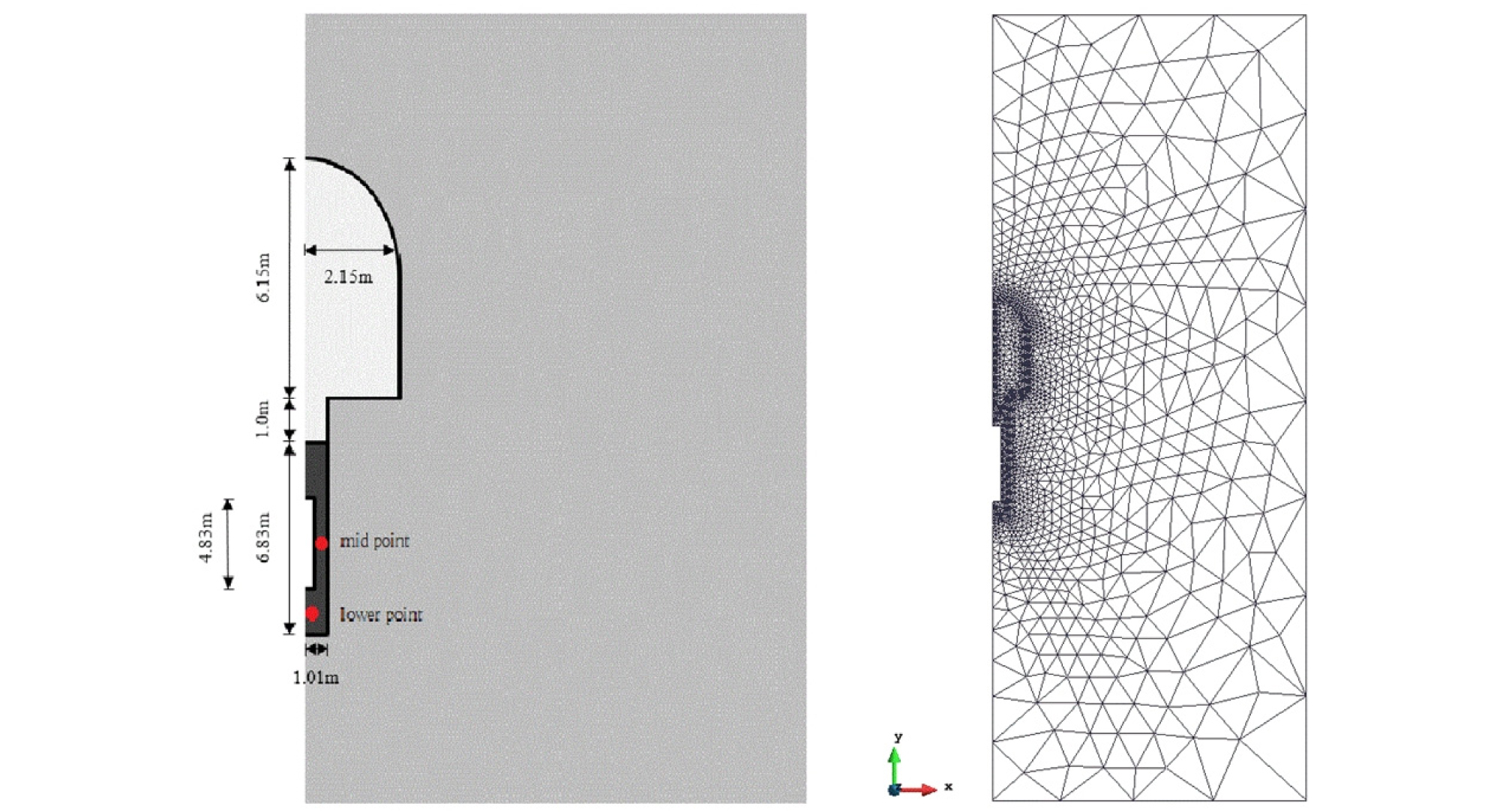
Based on the design criteria of the Korean Reference Disposal System (Lee et al., 2011), the model has assumed axisymmetric conditions using the mesh shown in Figure 3 for a numerical analysis, assumed to be installed 500m deep underground and initially constant temperature of clay buffer, clay sand mixture backfill. In fact, since the disposal hole is a cylindrical shape, the 3D analysis will be accurate, but the 2D analysis was performed considering the efficiency. The 2D model was set along the diameter, considering that the swelling pressure of the cross-section where the bentonite is thickest would act the greatest.
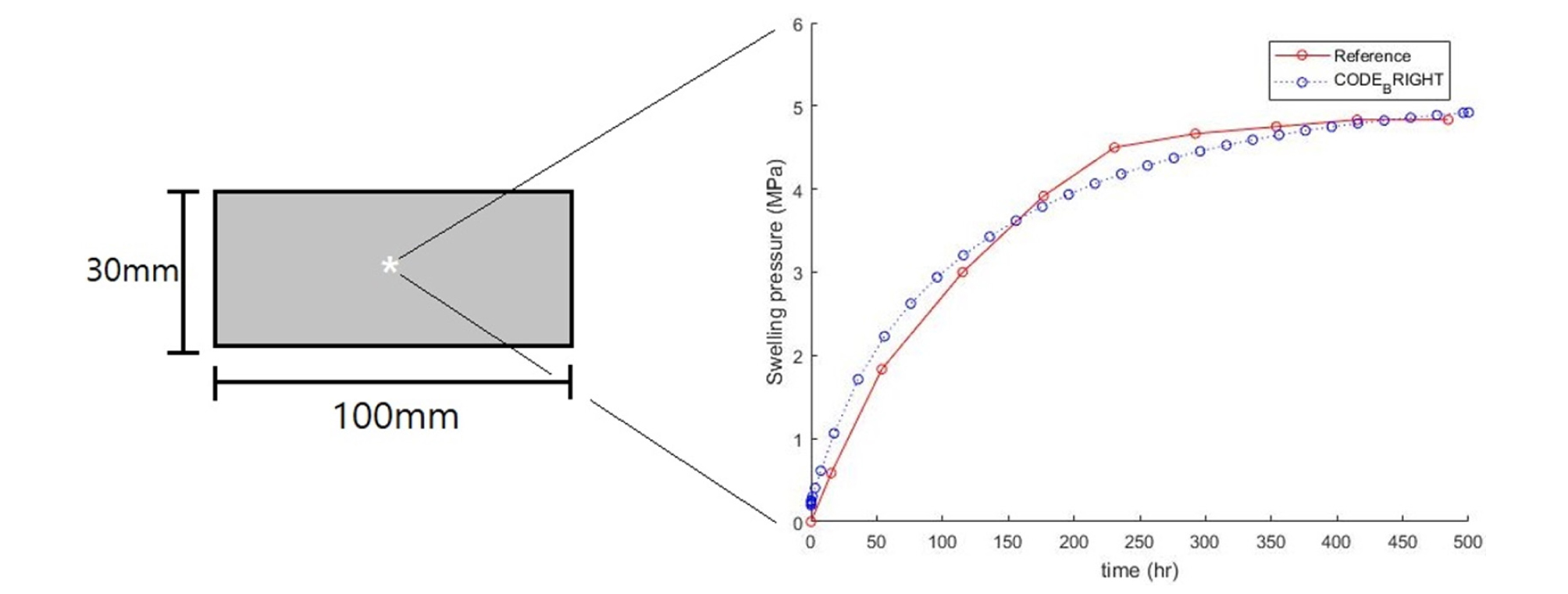
2.2.2 Verification
Fig. 4 shows a variation of the swelling pressure of the simple full-scale engineered barrier experiment (FEBEX) bentonite buffer compared with a theoretical value (Li et al., 2013). BBM is used to represent the unsaturated soils.
| $$d\varepsilon_{nu}^e=d\varepsilon_{\nu p}^e+d\varepsilon_{\nu s}^e+d\varepsilon_{\nu T}^e$$ | (16) |
| $$d\varepsilon_{\nu p}^e=\frac{k_i}\nu\frac{dp'}{p'}$$ | (17) |
| $$d\varepsilon_{\nu s}^e=\frac{k_s}\nu\frac{ds}{s+p_{at}}$$ | (18) |
| $$d\varepsilon_{\nu T}^e=\alpha_\nu\bigtriangleup T$$ | (19) |
where υ is the Poisson's ratio, p΄ is the mean stress, s is the suction pressure, pat is the gas pressure of the porous media, αv is the thermal expansion coefficient, kt is the bulk modulus, and ks is the liquid swelling and shrinking coefficient.
The FEBEX bentonite sample which was used was a sample of 100 mm in diameter and 30 mm in height with a fixed volume, porosity of 0.42 and initial degree of saturation as 23.8%, wetted at the bottom by a constant water pressure of 0.1 MPa. Data are based from many THM experimental results which are given in the literature. The peak swelling pressure of the reference value was 4.8 MPa, however the peak swelling pressure of the CODE_BRIGHT model was 4.9 MPa. The saturation time was different, however the final swelling pressure was similar.
2.2.3 Boundary condition
In this analysis, the boundary condition was set as the actual condition. The boundary domain was designated as roller so that the displacement in the normal direction of the interface was not generated. Self-weight load was set to be in the entire surface. The rock mass was set to 13 MPa, and the weight of buffer and backfill was set to 0.2 MPa. As a thermal constraint, the boundary condition was set to 20°C in the whole area and the analysis was performed.
The multiple fluid flow is represented by Darcy's Laws, and the parameters of liquid and gas phase are the fluid pressure (Pl) and the gas pressure (Pg), respectively. First, in the case of the surrounding rock mass, the pressure of the fluid was set as 5 MPa with the step function and the pressure of the gas was set as 0 MPa. Initial bentonite and bentonite sand mixture liquid pressures were determined by its initial saturation based on the Van Genuchten model. During the analysis, no flow was assumed in the canister part.
In a rock mass, existence of fractures results in large variations of permeability in each zone. However, in this analysis, no variation of porosity was considered because the low permeability of the bentonite controls the rate of water inflow. The initial granite porosity was assumed as 0.01. Initial porosity of backfill and buffer were determined by their initial dry densities. The analysis state is simulating at the end of construction of buffer and backfill.
2.2.4 Numerical model set up
Input properties of buffer, backfill, and rock used in this study are listed in the following tables. All data were taken from the Data report / Mariner et al., 2011, Åkesson et al., 2010, Toprak et al., 2013.
Table 2. Input data of granite for numerical model (Mariner et al., 2011)
Table 3. Input data of backfill for numerical model (Åkesson et al., 2010)
Table 4. Input data of buffer for numerical model (Åkesson et al., 2010, Toprak et al., 2013)
A sensitivity analysis was performed to pick up the major factor to generate the swelling pressure in a deep geological repository. Nowadays the safety standards for HLW disposal facilities in Korea are set with reference to foreign criteria. Therefore this study was carried out with the view that is necessary to establish a new standard in accordance with the type of bentonite in Korea. In fact, the factors that can be changed in the constructing process were selected. Five factors were selected: installation depth, initial dry density of buffer, initial water content of buffer, initial dry density of backfill, and initial elastic slope related to the changes in net mean stress and suction of buffer (kio), when the suction is zero, the slope kio gradually decreases to zero as suction turns positive. For an accurate analysis, reasonable minimum and maximum values of the input parameters were required. Range of input parameters was set as shown in the following table.
Table 5. Experimental domain of sensitivity anlaysis
| Properties | Unit | Minimum | Maximum | Reference |
| Installation depth | m | 300 | 700 | Kwon, 2012 |
| Initial dry density of buffer | kg/m3 | 1400 | 1600 | Saba, 2014 |
| Initial saturation of buffer | % | 20 | 50 | |
| Initial dry density of backfill | kg/m3 | 1400 | 1600 | |
|
Initial elastic slope for specific volume-mean stress of buffer | 0.05 | 0.125 | Åkesson et al., 2010 Toprak et al., 2013 |
In using the Latin Hypercube Sampling(LHS), 20 uniform samples were extracted for the sensitivity analysis. For each sample, Gaussian Kriging models were applied with the SCAD penalty for building metamodels and futhermore, the Variance Based Sensitivity Analysis(VBSA) was applied.
3. Results and Discussion
3.1 Swelling pressure performance
Saturation at the mid point and the bottom of the buffer were measured. The analysis was based on MX-80 property and Korean repository criteria with initial saturation set as 55%. At both points, the saturation of buffer generally rises rapidly in the initial stage. A change in saturation time was observed depending on the measurement position. Due to the difference in distance from the bed rock, the buffer below the canister was slowly saturated. The buffer at the midpoint showed full saturation after 10 years of installation, but the buffer at the lower point showed full saturation after 15 years of installation.
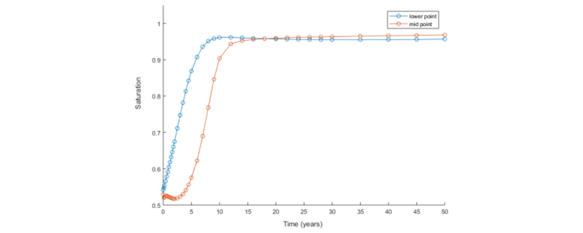
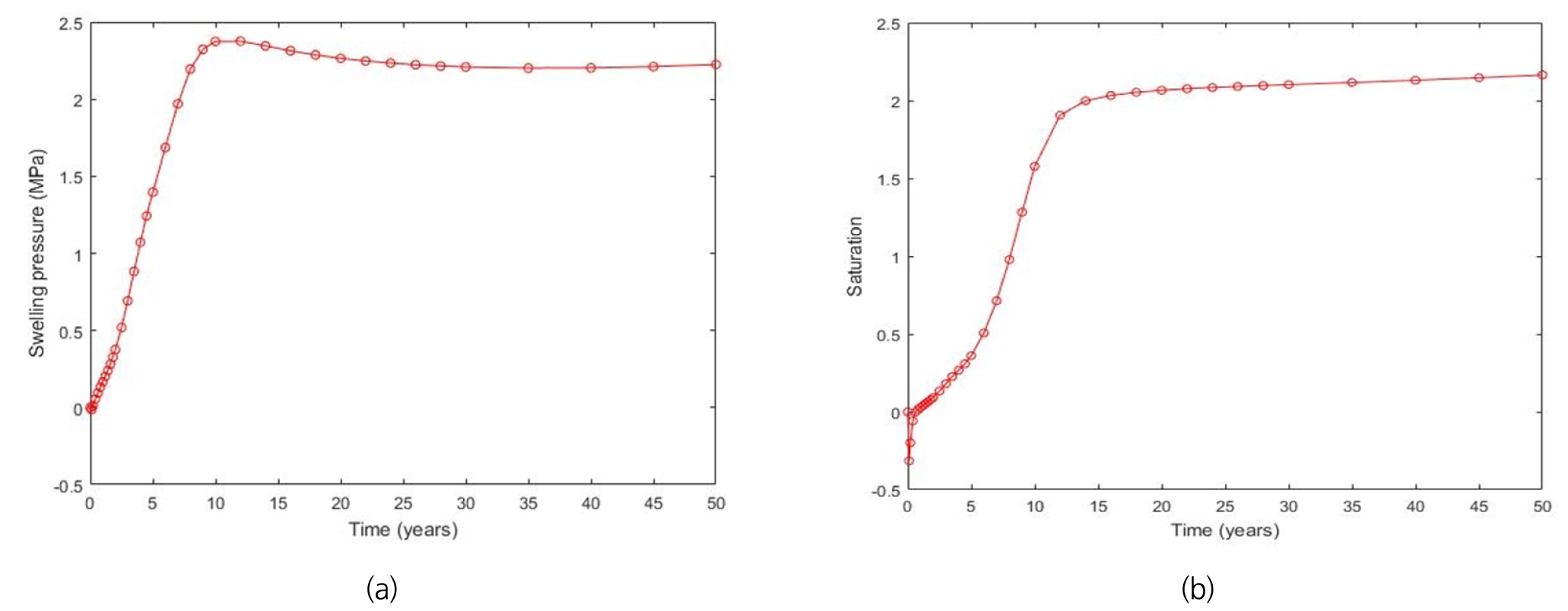
Fig. 6 shows the variation of swelling pressure based on MX-80 property with initial saturation set as 55%. This simulation result indicates the variation of swelling pressure. The swelling pressure generally rises rapidly in the initial stage. After the initial stage, it converges. This result is also theoretically predictable. Because of the low initial saturation, the initial liquid pressure in the buffer is measured to be very large.
Because of the difference in saturation time, the different shape of the swelling pressure formation occurs. The mid point of buffer in which the saturation time was slightly faster than the lower point, showed a peak swelling pressure, and a small decrease in convergence. However, the buffer at the lower point, where the saturation time was relatively slow, was able to observe a small decrease in the swelling pressure at the very early stage.
The reason why the swelling pressure converges after taking the peak value in the fast hydration and decreasing is as follows. The overall grain orientation of the bentonite in the dry state is generally random. However, the continuous ground water flow creates an increased interparticle distance. This leads to a lower shear strength in the inter-aggregate contact regions. Because of the above reasons, the high pressure generated by water inflow easily displaces and deforms the particles. As a result, the pressure decreases after the first peak. More water uptake causes the aggregated particle clay to be homogeneous and dispersed.
A small decrease of the swelling pressure at the very early stage in the buffer at lower point attributed to the self weight.
Due to the reduction in swelling pressure because of bentonite rearrangement, the swelling pressure at the mid point appeared to be greater. Since the safety of the deep geological repository should be the most important factor in the design process, in the sensitivity analysis process, the mid point of the buffer was set as a target point where the highest swelling pressure was observed.
3.2 Sensitivity analysis
The constants of the metamodel obtained by using 20 uniform samples and output data of the selected sample, which is the peak swelling pressure of the buffer are as follows. Based on the constructed metamodel, the VBSA referred to as Sobol’s method was used (Sobol, 2001, Sobol, 1993). Table 6 provides the sensitivity indices. Fig. 7 shows the noise of the selected inputs. The greater the change in the graph, the greater the influence of the main effect.
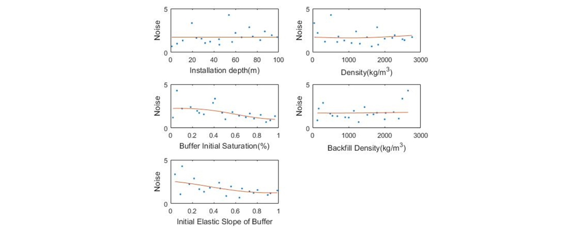
Table 6. Constants of metamodels based on Gaussian Kriging theory
| Parameters | Constants |
| µ | 1.97 |
| σ2 | 8.87E-01 |
| θ1 | 3.64E-10 |
| θ2 | 1.70E-06 |
| θ3 | 1.14E-02 |
| θ4 | 2.89E+01 |
| θ5 | 5.68E+02 |
Table 7. Sensitivity indices obtained by VBSA
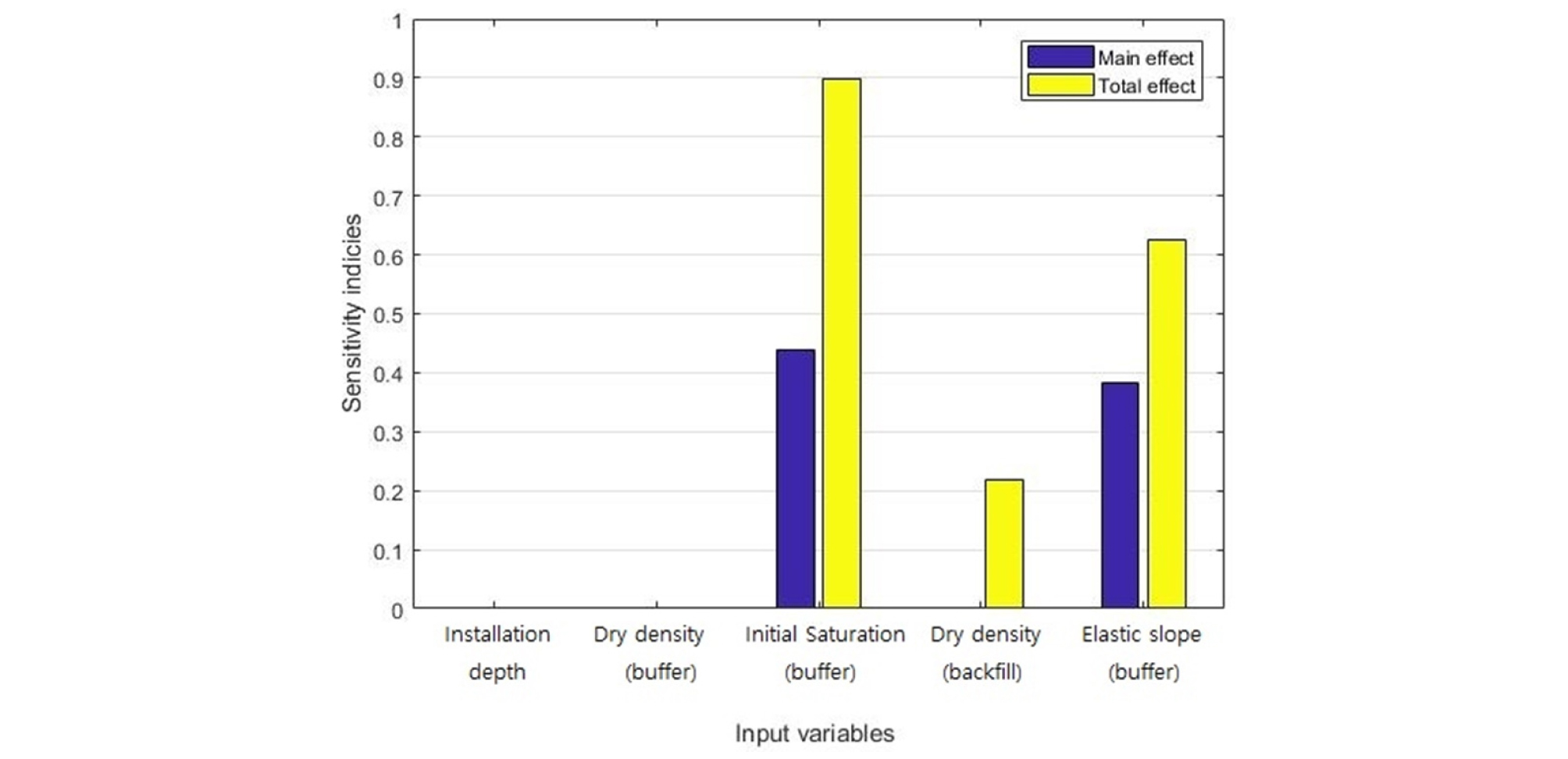
The results show that the major factors are the initial saturation of the buffer and the initial elastic slope for specific volume-mean stress of buffer. The sensitivity indices of initial saturation and slope sensitivity were 0.44 and 0.38. The representing for remaining factors was less than 0.01, which mean that the swelling pressure is not significantly affected. Considering the combined influence of the factors, the initial density of the backfill also appears to have a major impact. The first-order interaction between the initial saturation of the buffer and the initial dry density of the backfill, and that between the initial saturation of the buffer and the initial elastic slope show significant relationships, in which values were 0.218 and 0.242, respectively.
From the results, it was found that the initial condition of backfill should also be considered when designing the deep geological repository. This is in contrast to the most of the design standards focused on the bentonite. Initial elastic slope of buffer was also found to be a factor influencing the swelling pressure. This is a unique property of bentonite itself and depends on the type of bentonite. Korea’s deep geological repository criteria have been made with reference to foreign standards, nevertheless Korea uses a Gyeongju calcium bentonite as a buffer material, while foreign countries use bentonites produced in their own countries. Therefore, it is necessary to study the characteristics of bentonite in Korea and establish more proper standards.
4. Conclusions
This study focuses on the sensitivity analysis of various initial factors and determine of the major factor on the generation of swelling pressure in the bentonite buffer of a deep geological repositories, whereas previous studies focused on a single factor affecting swelling pressure. By considering the hydro-mechanical relationships, numerical studies were conducted to investigate major factors which have a great effect on the swelling pressure. The main findings are as follows:
The saturation time varies depending on the observation point. As soon as saturated, the peak swelling pressure was observed and afterwards converged, which would be critical to the stability of the barrier. On the other hand, the swelling pressure slowly converges at the point where the saturation time was very slow. There was no significant difference in the swelling pressure between points, but the mid point of the buffer showed the slightly larger swelling pressure and it would be a critical point in the deep geological repository design process.
The initial saturation of buffer and initial elastic slope for a specific volume-mean stress of buffer have a great effect on the generation of swelling pressure. The dry density of the backfill does not have an influence to the swelling pressure by the factor itself, but it was found to have a large second-order interaction between dry density and initial saturation of the buffer.
Based on the research results, the initial degree of saturation of the buffer is the most important factor for the swelling pressure generation. A precise setting of initial buffer saturation is required for a safety deep geological repository design. However, the initial dry density of the backfill also appears to be a major factor in combination with the degree of saturation of the buffer. It is necessary to develop new criteria considering the initial backfill condition. The initial elastic slope of buffer was also found to have a great influence, which is dependent on the type of bentonite. Accordingly, a swelling pressure criterion appropriate to the bentonite used in a specific country is required.
For the further study, long term stability is crucial to the stability of HLW repositories. 50 years is a very short time in terms of long-term behavior. An analysis of long-term behavior is requisite. Also depending on the location of the repository, the chemical properties of the groundwater may also affect the behavior of the buffer. The consideration of chemical composition in underground water is needed. The heat generated from the disposal material is also a key factor in the stability of the HLW disposal facility. Heat is also related with hydro-mechanical property. The THM coupled numerical analysis is required.
